Pulse modulation power amplifier with enhanced cascade control method

a power amplifier and enhanced cascade technology, applied in power amplifiers, amplifiers, electric devices, etc., can solve the problems of low efficiency and heat dissipation, prior art in the field has not provided solutions with an acceptable audio quality, and the use of digital power amplification has been limited

Inactive Publication Date: 2001-10-02
BANG & OLUFSEN +1
View PDF13 Cites 99 Cited by
  • Summary
  • Abstract
  • Description
  • Claims
  • Application Information

AI Technical Summary

Benefits of technology

The above objectives are obtained with the present invention. In the first preferred embodiment, an amplifier according to the invention is particular in that negative feedback is introduced from the switching power stage output to one or several loops feeding into one or several pre-amplifier stages preceding the modulator. This offers a range of advantages that are new to the art, in terms of performance and stability control. A further embodiment of the invention is particular in that the local feedback has a enhanced cascaded structure with a single feedback path, that comprises a filter with a phase characteristic such that a pole in the demodulation filter is compensated.
Means for obtaining improved elimination of noise from the noisy feedback by using a notch filter and high frequency poles in the local feedback or alternatively forward path. This improves distortion when carrier based pulse width modulation is used.

Problems solved by technology

Nearly all commercially available power amplifiers for frequencies in the above range are of the linear analog type: class A, AB, and B. Since the output transistors of such amplifiers operate in the linear region, they have a low efficiency and dissipate a considerable amount of heat.
Despite this efficiency advantage, prior art in the field has not provided solutions with an acceptable audio quality, that could make them generally useful and direct replacements for analog amplifiers.
Accordingly, the use of digital power amplification has been limited to applications where the demands for output quality are low.
However, there are numerous non-ideal features with this method:
The post filter errors will introduce further distortion, since magnetic core materials are not ideal.
The non-controlled digital switching amplifier is therefore not robust and reliable.
However, the poles of the low pass filter cause a large phase shift which puts strong restrictions on loop design.
Consequently, reasonable loop bandwidths requires high switching frequencies.
This causes several problems, such as lower efficiency, and poor performance due to the first two errors mentioned above.
However, the high frequency content at the power stage output makes the feedback source potentially very noisy.
Furthermore, a number of the above errors are not (or only partially) compensated
The fundamental problem of both methods are the conflicting desires for a low carrier frequency, high gain-bandwidth product and good stability characteristics in all situations.
A further problem with prior art arrangements is the apparent complexity of the system, partially caused by inefficient control.

Method used


Image

  • Pulse modulation power amplifier with enhanced cascade control method
  • Pulse modulation power amplifier with enhanced cascade control method
  • Pulse modulation power amplifier with enhanced cascade control method

Examples


fourth embodiment

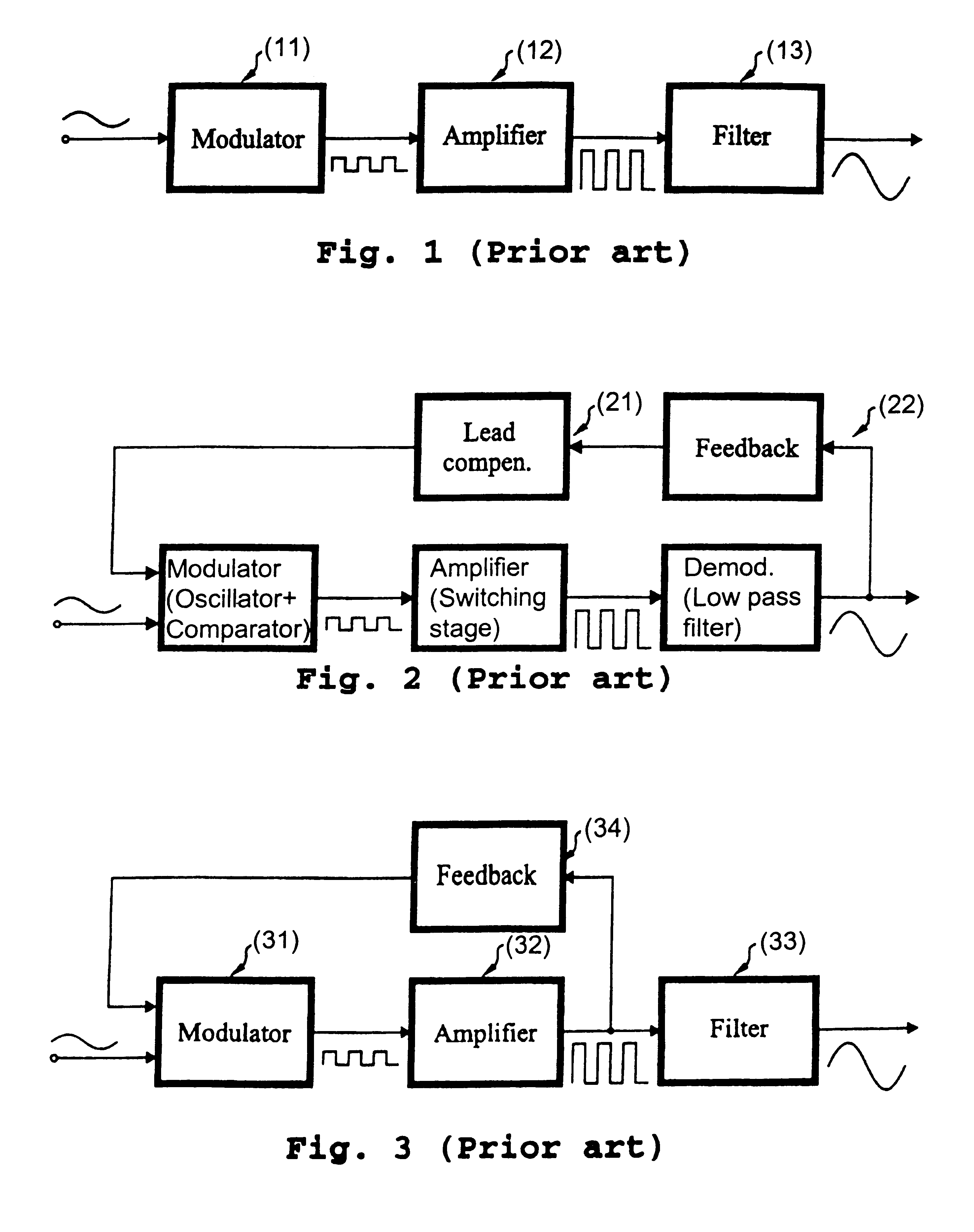
The lowpass characteristic of the feedback path is beneficial in several aspects. It causes a closed loop zero-pole phase lead characteristic which can be very useful for realizing a cancellation of one of the poles of the demodulation filter. Furthermore, the pole causes an important filtering of the high frequency switching noise from the power stage output, which is essential when carrier based modulation methods are used (the invention). In this simple exanplary embodiment the initial forward block is a simple gain, with a gain that leads to a constant open loop and closed loop gain of K in the frequency band of interest: ##EQU2##

Whereas the i'th block has a pole-zero characteristic to compensate for the zero-pole characteristic of the preceding loop: ##EQU3##

By this realization the open loop gain of the single loop configuration can be written by the following 1. order expression: ##EQU4##

It is easy to show that for all loops: ##EQU5##

The closed-loop transfer function can be ap...

first embodiment

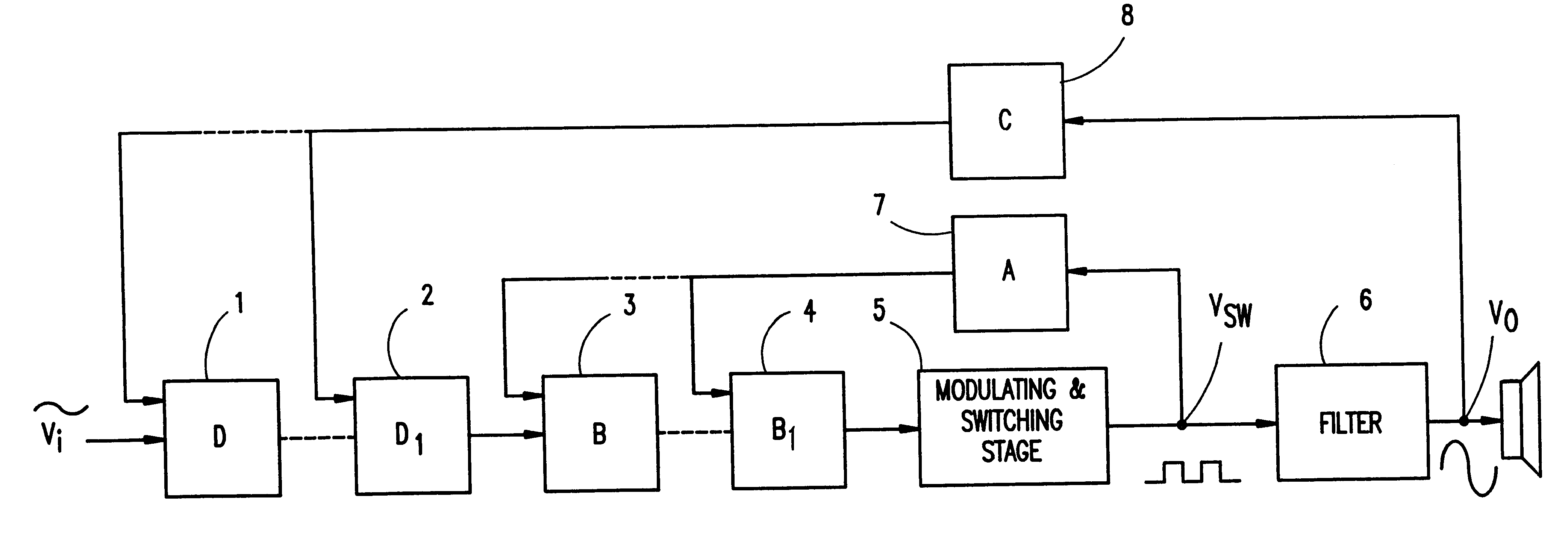
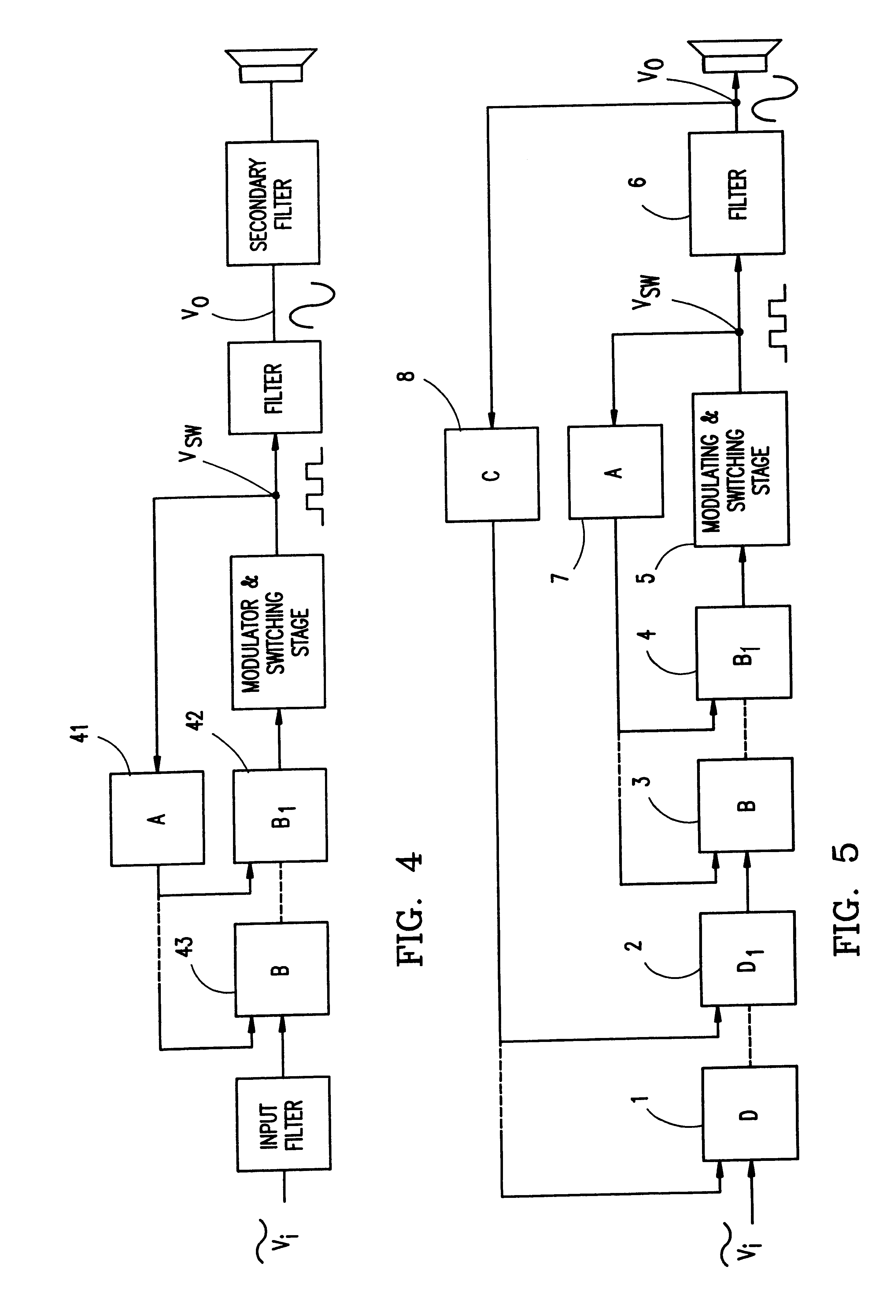
The second embodiment of the invention involves the extension of the first embodiment to a dual feedback Multivariable Enhanced Cascade Control (MECC)structure, were the two cascades are closely connected. A general block diagram is illustrated in FIG. 5. The system relies on the zero-pole lead characteristic caused by the single lowpass feedback path of the local enhanced cascade. Due to the use of two feedback sources, this embodiment is termed Dual feedback Multivariable Enhanced Cascade Control. The second cascade has the same special characteristics as the first cascade with only one single feedback path C and a set of forward path blocks D.sub.i. One preferred approach of dual feedback MECC design is based on the local enhanced cascade in FIG. 6a and illustrated in FIG. 6b. The main reconstruction filter F(s) is assumed to be 2. order. The feedback path has a constant gain characteristic: ##EQU7##

The initial block forward block D.sub.1, is a simple gain block with a gain in th...

third embodiment

THE INVENTION

A further preferred embodiment regarding modulator implementation for the MECC digital power amplifier is a Controlled self-Oscillating Pulse Modulator, new to the art. An example of an embodiment realizing this method is shown in FIG. 10. The preferred method is characterized by having a non-hysteresis comparator as a modulator and by modifying the first local loop to a have higher order characteristic, by an additional pole in both forward path block B.sub.1 and feedback path A. This secures controlled and stable self-oscillating conditions. The desired pulse modulation effect is then obtained by superposing the oscillating signal with the signal input (V.sub.i). FIG. 11 shows an example of the signal characteristics at the reference point for the modulator where the oscillating signal is superposed with the input signal. Furthermore, the pulse modulating effect is shown.

Advantages of the above described Controlled self-Oscillating Pulse Modulator over constant freque...


PUM


Abstract

A digital switching power amplifier with Multivariable Enhanced Cascade Controlled (MECC) includes a modulator, a switching power stage and a low pass filter. In the first preferred embodiment an enhanced cascade control structure local to the switching power stage is added, characterised by having a single local feedback path A (7) with a lowpass characteristic and local forward blocks B1 or B (3, 4). The leads to a much improved system with a very low sensitivity to errors in the switching power stage. In the second preferred embodiment of the invention the control structure is extended with a global structure composed of a single feed-back path C (8) and forward paths blocks D1 or D (1, 2). This provides further improvements and a very low sensitivity to load variations and filter errors. Both MECC embodiments are characterised by being simple in implementation, stable and extendible by adding / removing simple local (3) or global (1) forward path blocks. A third embodiment of the invention is a controlled self-oscillating pulse modulator, characterised by first a non-hysteresis comparator as modulator and second by a higher order oscillating loop realized in both forward path B1 and feedback path A to determine stable self-oscillating conditions. An implemented 250W example MECC digital power amplifier has proven superior performance in terms of audio performance (0.005% distortion, 115 dB dynamic range) and efficiency (92%).

Description

This invention relates to a power amplifier for the audio frequency range, comprising a pulse modulator, a power amplifier stage for amplifying the modulated signal, the output of which is low pass filtered in a demodulation filter for obtaining an analog output to feed to a consumer.1. BackgroundNearly all commercially available power amplifiers for frequencies in the above range are of the linear analog type: class A, AB, and B. Since the output transistors of such amplifiers operate in the linear region, they have a low efficiency and dissipate a considerable amount of heat. The basic pulse modulation ("digital") switching class D power amplifier method in theory provides a much higher efficiency, which lowers the amplifier volume and heat development. Despite this efficiency advantage, prior art in the field has not provided solutions with an acceptable audio quality, that could make them generally useful and direct replacements for analog amplifiers. Accordingly, the use of dig...

Claims


Application Information

Patent Timeline
Patent Type & Authority Patents(United States)
IPC IPC(8): H03F1/08H03F3/20H03F3/217H03F1/34
CPCH03F1/083H03F3/217H03F2200/331
Inventor NIELSEN, KARSTEN
Owner BANG & OLUFSEN
Why Eureka
Try Eureka