Voltage clamping system and method for a DC/DC power converter

a voltage clamping system and power converter technology, applied in the direction of electric variable regulation, process and machine control, instruments, etc., can solve the problems of voltage spike across the power switch, lower conversion efficiency of the converter, loss of energy,

Inactive Publication Date: 2001-11-06
PHILIPS ELECTRONICS NORTH AMERICA
View PDF34 Cites 80 Cited by
  • Summary
  • Abstract
  • Description
  • Claims
  • Application Information

AI Technical Summary

Problems solved by technology

Converters in this class present a unique problem, in that the conversion topology does not inherently define the mechanism by which the transformer's core is to be reset during the OFF period of the switch.
As a result the converter has lower conversion efficiency, i.e., loss of the energy inherent in the spike to heat.
The leakage inductance of the transformer

Method used


Image

  • Voltage clamping system and method for a DC/DC power converter
  • Voltage clamping system and method for a DC/DC power converter
  • Voltage clamping system and method for a DC/DC power converter

Examples


example 2

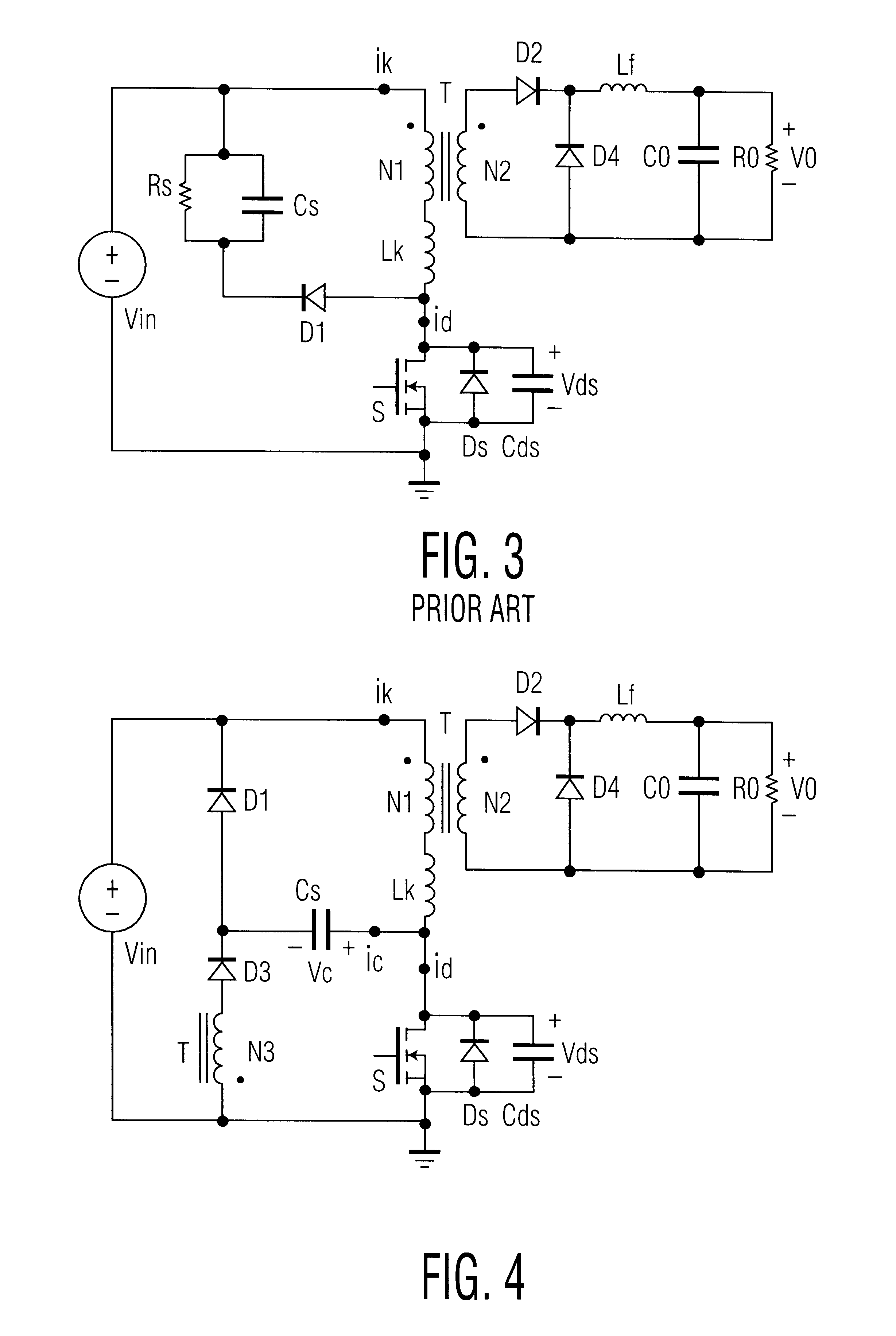
In accordance with embodiments of the invention, the circuit according to example 1 provides a basis for enhancements, as shown in FIGS. 6 and 7, whose principle of operation is similar to FIG. 4.

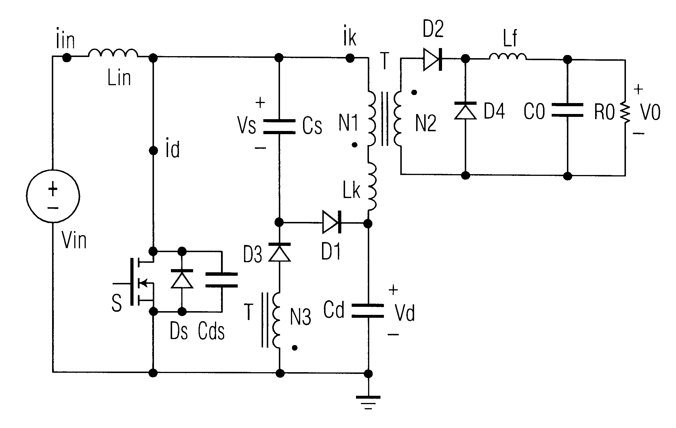
When switch S is turned ON, the input source voltage V.sub.in charges inductor L.sub.in, and the input current i.sub.in linearly increases. Capacitor C.sub.s discharges through switch S, diode D3 and winding N3. This discharging current is coupled to the winding N2 to supply the load. At the same time, the voltage V.sub.d is applied to the primary winding N1, and also supplies the load. When switch S is turned OFF, the inductor current i.sub.in charges capacitor C.sub.d through a loop L.sub.in -N1-L.sub.k -C.sub.d -V.sub.in. The leakage energy is transferred to the capacitor C.sub.s through diode D1 and the capacitor voltage V.sub.s is applied to the primary winding N1. When the induced voltage across winding N3 is higher than voltage V.sub.d, diode D3 turns on and the magnetizing energy is...

second embodiment

Since the circuit is a current fed power converter, it is suitable for power factor correction applications. FIG. 7 shows the power factor correction circuit, provided by replacing the V.sub.in with AC line input and a full wave diode bridge rectifier DB as compared with FIG. 6.


PUM


Abstract

A voltage boost power converter circuit, having an input inductor, active switch, and a transformer having primary, secondary and auxiliary windings. A clamping capacitor and a first passive switch are in series across the primary winding. The auxiliary winding and a second passive switch are in series, connected to the node between the clamping capacitor and first passive switch. The active switch is connected between ground the primary winding. A bulk capacitor forms a series loop including the active switch and primary winding. The method efficiently resets a the transformer, by transferring power to a load through the primary winding, and discharging a clamping capacitor through a separate inductively linked winding of the transformer during an ON state; and clamping the active switch voltage with the clamping capacitor, charging the clamping capacitor with a leakage inductance of the transformer, and charging the bulk capacitor during an OFF state.

Description

The present invention relates to the field of switching power transfer devices, and more particularly to an improved voltage clamping method for a DC / DC power converter.The present invention relates to the class of DC-to-DC converters that incorporate the topology represented in FIG. 1. A converter in that class is referred to as a "single ended forward" converter because power flow is gated by a single switch and energy is transferred forward, from the primary winding to the secondary winding of the transformer, during the ON period of the switch. Converters in this class present a unique problem, in that the conversion topology does not inherently define the mechanism by which the transformer's core is to be reset during the OFF period of the switch. A number of solutions are proposed in the prior art, each with different tradeoffs in the cost of the converter, as well as its efficiency and power density.A well-known prior art DC / DC forward converter is shown in FIG. 2A, where L.s...

Claims


Application Information

Patent Timeline
IPC IPC(8): H02M3/24H02M3/335H02M1/34H02M3/28
CPCH02M1/34H02M3/33538H02M2001/346Y02B70/1491Y02B70/10H02M1/346H02M3/335
Inventor QIAN, JINRONGWENG, DA FENG
Owner PHILIPS ELECTRONICS NORTH AMERICA
Why Eureka
Try Eureka