Apparatus and method for preparing microparticles

a microparticle and apparatus technology, applied in the field of preparation of microparticles, can solve the problems of large equipment, large yield loss, and unpredictable scale-up, and achieve the effects of narrow or tighter target microparticle size range, large yield loss, and large yield loss

Inactive Publication Date: 2001-12-18
ALKERMES INC
View PDF32 Cites 35 Cited by
  • Summary
  • Abstract
  • Description
  • Claims
  • Application Information

AI Technical Summary

Benefits of technology

A significant advantage of the present invention is that it provides a method for controlling particle size distribution. By controlling particle size distribution, yield losses, resulting from microparticles that fall outside of a desired microparticle size range, can be substantially reduced or eliminated. This makes the present invention particularly useful for commercial products.
is that it provides a method for controlling particle size distribution. By controlling particle size distribution, yield losses, resulting from microparticles that fall outside of a desired microparticle size range, can be substantially reduced or eliminated. This makes the present invention particularly useful for commercial products.
The present invention also advantageously allows for use of a more narrow or tighter target microparticle size range than in conventional processes. Narrowing the limit for the microparticle size range typically results in larger yield losses. These yield losses can be avoided or minimized by achieving a more narrow microparticle size distribution through the process of the present invention.
The present invention provides a method and apparatus that are particularly advantageous for scale-up. The parallel path manifold of the present invention allows for capacity increases from an established (single path) system without full-scale trial and error experiments in new and different equipment. The total flow rate can be increased from the single path system based upon the number of flow streams in the manifold.
The present invention is described with reference to the accompanying drawings. In the drawings, like reference numbers indicate identical or functionally similar elements.
FIG. 2 shows a static mixer suitable for use with the present invention;

Problems solved by technology

Scale-up into new, larger equipment is often unpredictable and achieved in large measure through trial and error.
However, the economic costs of large-scale trial and error experiments can be prohibitive.
Even in an efficient commercial production process, some percentage of the microparticles produced will be larger than the upper size limit, and some percentage of the microparticles produced will be smaller than the lower size limit, resulting in yield losses.
Typically, the more narrow or tighter the desired microparticle size range, the larger the yield losses that result.
Narrowing the limit for the microparticle size range typically results in larger yield losses.

Method used


Image

  • Apparatus and method for preparing microparticles
  • Apparatus and method for preparing microparticles
  • Apparatus and method for preparing microparticles

Examples


example 1

Static Mixer Tests

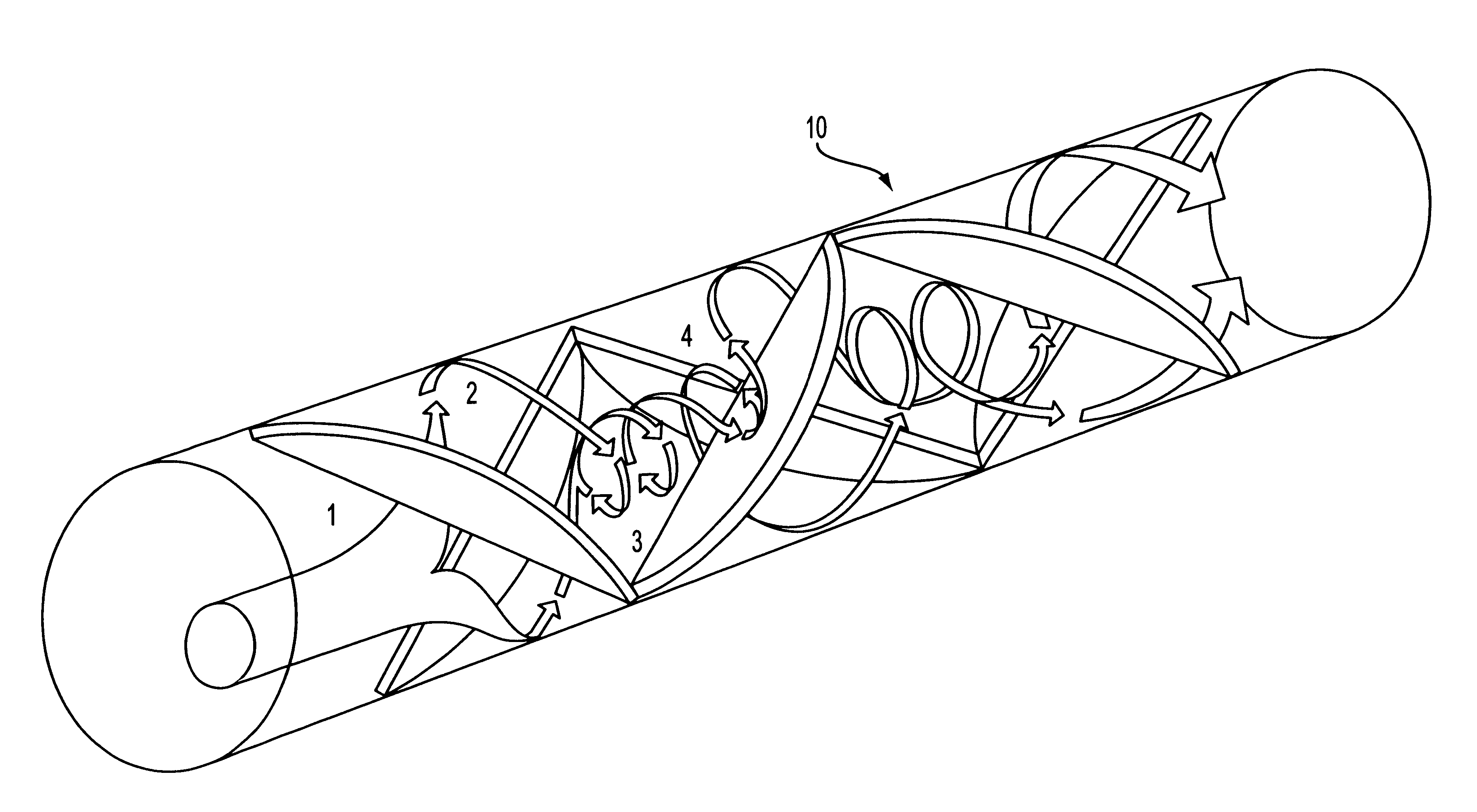
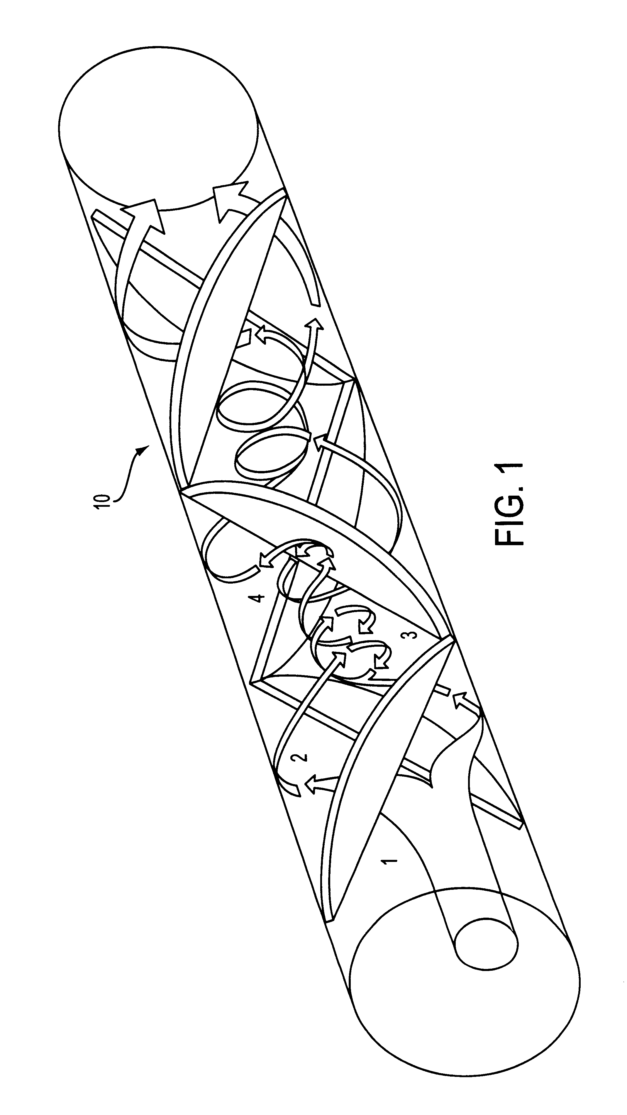
A test program was conducted using a variety of static mixers. A static or motionless mixer consists of a conduit or tube in which is received a number of static mixing elements. Static mixers provide uniform mixing in a relatively short length of conduit, and in a relatively short period of time. With static mixers, the fluid moves through the mixer, rather than some part of the mixer, such as a blade, moving through the fluid. Flow through one type of static mixer is illustrated in FIG. 1. A pump (not shown) introduces a stream of one or more fluids into a static mixer 10, as shown generally at 1. The stream is split and forced to opposite outside walls, as shown generally at 2. A vortex is created axial to the centerline of static mixer 10, as shown generally at 3. The vortex is sheared and the process recurs, but with the opposite rotation, as shown generally at 4. The clockwise / counterclockwise motion ensures a homogeneous product.

One example of a static mixer...

example 2

Preparation of Risperidone Microparticles Using a Manifold

Microparticles comprising risperidone were prepared at the 20-kilogram scale. The 20 Kg process (8 Kg of active agent and 12 Kg of polymer) provides a theoretical drug loading of the microparticles of 40% (8 Kg / 20 Kg.times.100%).

The polymer solution was prepared by dissolving 12.0 Kg of MEDISORB.RTM. 7525 DL polymer (Alkermes, Inc., Blue Ash, Ohio) in 60 Kg of ethyl acetate (Merck). The polymer was added to the solvent at 25.degree. C. in a stainless steel reactor. The temperature of the tank was raised to 37.degree. C. to facilitate dissolution. The vessel was agitated for at least 16 hours to dissolve the polymer. Once dissolved, the solution temperature was reduced to 25.degree. C.

The drug solution was prepared by dissolving 8.0 Kg of risperidone base (Janssen Pharmaceutica, Beerse, Belgium) in 25.3 Kg of benzyl alcohol (Merck) at 25.degree. C. in a stainless steel reactor. The organic phase was prepared by adding the drug...

example 3

Methods for Preparing Microparticles

As exemplified by the examples discussed above, methods for preparing microparticles in accordance with the present invention will now be described in more detail. In one embodiment of the present invention, a first phase, comprising an active agent and a polymer, is prepared. In one embodiment of the present invention, the first phase is prepared by dissolving the active agent in a first solvent to form an active agent solution. The polymer is dissolved in a second solvent to form a polymer solution. The active agent solution and the polymer solution are blended to form the first phase. In a particularly preferred embodiment, the active agent is selected from the group consisting of risperidone, 9-hydroxyrisperidone, and pharmaceutically acceptable salts thereof. In such an embodiment, a preferred first solvent is benzyl alcohol, and a preferred second solvent is ethyl acetate.

In another embodiment of the present invention, the first phase is pre...


PUM

PropertyMeasurementUnit
residence timeaaaaaaaaaa
diameteraaaaaaaaaa

Abstract

Apparatus and method for preparing microparticles. An emulsion is formed by combining two phases in a static mixing assembly. The static mixing assembly preferably includes a preblending static mixer and a manifold. The emulsion flows out of the static mixing assembly into a quench liquid whereby droplets of the emulsion form microparticles. The residence time of the emulsion in the static mixing assembly is controlled to obtain a predetermined particle size distribution of the resulting microparticles.

Description

1. Field of the InventionThe present invention relates to preparation of microparticles. More particularly, the present invention relates to a method and an apparatus for preparing microparticles having a more controlled and symmetrical particle size distribution.2. Related ArtA variety of methods is known by which compounds can be encapsulated in the form of microparticles. It is particularly advantageous to encapsulate a biologically active or pharmaceutically active agent within a biocompatible, biodegradable wall forming material (e.g., a polymer) to provide sustained or delayed release of drugs or other active agents. In these methods, the material to be encapsulated (drugs or other active agents) is generally dissolved, dispersed, or emulsified, using stirrers, agitators, or other dynamic mixing techniques, in a solvent containing the wall forming material. Solvent is then removed from the microparticles and thereafter the microparticle product is obtained.Development of a mic...

Claims


Application Information

Patent Timeline
Patent Type & Authority Patents(United States)
IPC IPC(8): A61K9/16A61J3/00A61K9/58A61K31/517A61K47/34A61P25/18
CPCA61K9/1682A61K9/1694Y10T428/2985A61P25/18
Inventor LYONS, SHAWN L.WRIGHT, STEVEN G.
Owner ALKERMES INC
Why Eureka
Try Eureka