

Catalyst for purifying exhaust gas
a technology of catalyst and exhaust gas, which is applied in the direction of physical/chemical process catalyst, metal/metal-oxide/metal-hydroxide catalyst, separation process, etc., can solve the problems of cracking of the coating layer, inability to achieve high purification performance, and high temperature of exhaust gas of automobiles
- Summary
- Abstract
- Description
- Claims
- Application Information
AI Technical Summary
Problems solved by technology
Method used
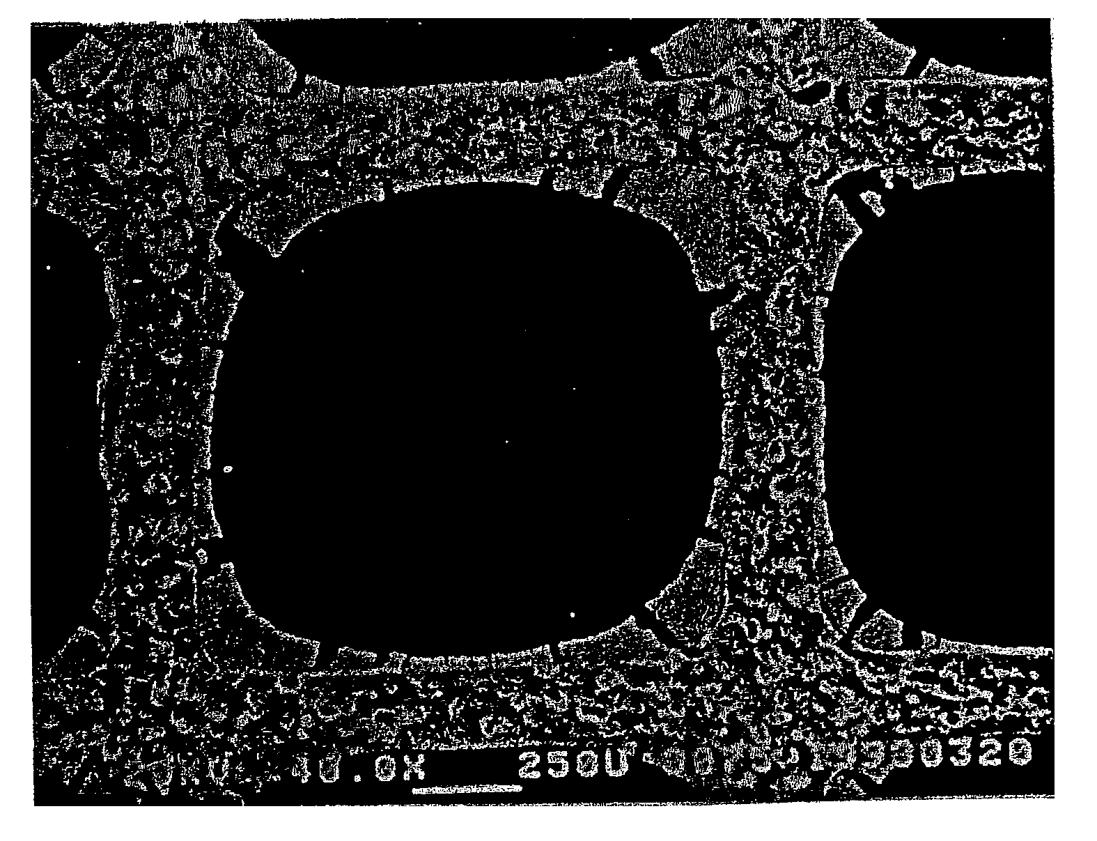
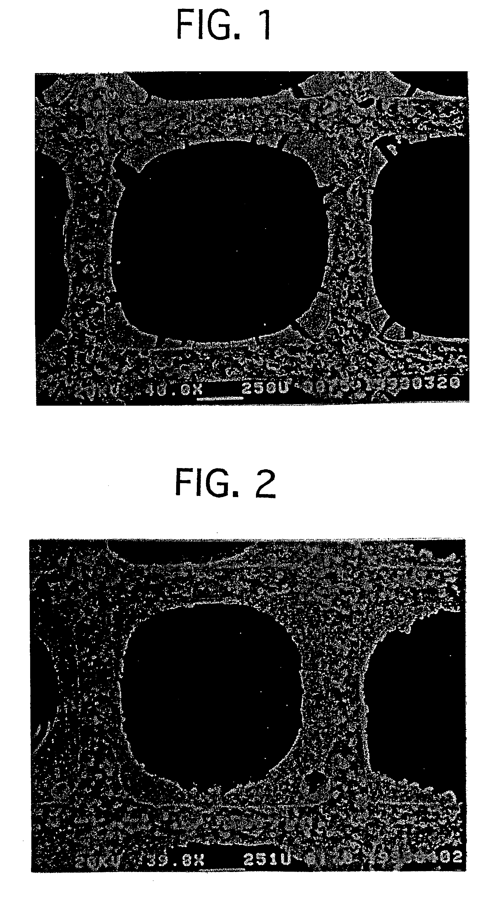
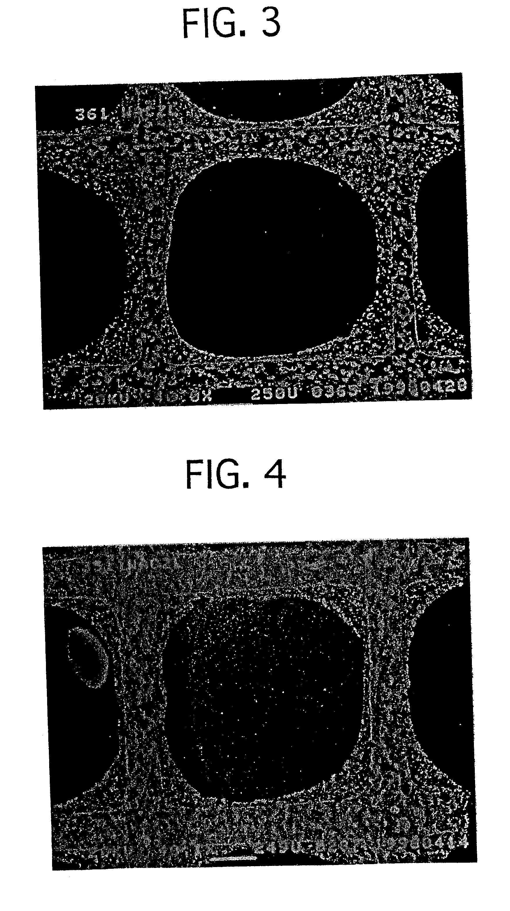
Image

Examples
example no.2
EXAMPLE NO. 2
Except that the activated alumina particle working as the porous oxide was replaced by the same amount of a zirconia particle having a specific surface area of 50 m.sup.2 / g, and that the aluminum nitrate and boehmite were replaced by 100 parts by weight of a zirconia sol (ZrO.sub.2 content: 10% by weight), an exhaust-gas-purifying catalyst of Example No. 2 was prepared in the same manner as Example No. 1. The average conversion was measured in the same manner as Example No. 1. The result is set forth in Table 1.
example no.3
EXAMPLE NO. 3
Except that a high-concentration aqueous solution was used in which aluminum nitrate, cerium nitrate and zirconyl oxynitrate were solved by ratios of "a"=0.5 and "b"=0.33 in the formula (3), an exhaust-gas-purifying catalyst of Example No. 3 was prepared in the same manner as Example No. 1. The average conversion was measured in the same manner as Example No. 1. The result is set forth in Table 1.
example no.4
EXAMPLE NO. 4
Except that a high-concentration aqueous solution was used in which aluminum nitrate, cerium nitrate, zirconyl oxynitrate and yttrium nitrate were solved by ratios of "a"=0.5, "b"=0.6 and "c"=0.05 in the formula (2), an exhaust-gas-purifying catalyst of Example No. 4 was prepared in the same manner as Example No. 1. The average conversion was measured in the same manner as Example No. 1. The result is set forth in Table 1.
PUM
| Property | Measurement | Unit |
|---|---|---|
| Temperature | aaaaa | aaaaa |
| Time | aaaaa | aaaaa |
| Time | aaaaa | aaaaa |
Abstract
Description
Claims
Application Information