Soft x-ray light source device

a light source device and soft x-ray technology, applied in photomechanical devices, instruments, nuclear engineering, etc., can solve the problems of limited range of application of such methods, reduced focal depth, and terms of patterns that can be used

Inactive Publication Date: 2002-01-15
NIKON CORP
View PDF4 Cites 51 Cited by
  • Summary
  • Abstract
  • Description
  • Claims
  • Application Information

AI Technical Summary

Problems solved by technology

In the past, methods such as improvement of the projection optical system, deformed illumination and phase shift mask methods, etc., have been proposed; however, there are difficulties in terms of the patterns that can be used, so that the range of application of such methods is limited.
At the same time, however, as is clear from Equation (2), this leads to the problem of a reduced focal depth.
Furthermore, an LPX is extremely compact as an apparatus compared to synchrotron radiation facility, etc.
Since soft X-rays are strongly absorbed by all substances, ordinary lenses and reflective mirrors cannot be used.
However, even in the case of reflective surfaces formed using such multi-layer films, the limit of the reflectivity obtained for soft X-rays is approximately 70%.
The development of such laser devices is currently being pursued; however, the development of a laser device which has such a large output, and which can operate stably over a long period of time, is not easy.
Furthermore, even if such a laser device is developed, the resulting device would be extremely expensive.
However, in cases where a laser plasma is actually used as a light source in soft X-ray lithography, there are various limitations on the conditions of plasma generation.
Accordingly, it is not always possible to discuss the problem in terms of conversion efficiency and output of the laser light source alone.
The first limitation is a limitation concerning the size of the plasma generated in a case where the illumination of the mask is taken into account.
Since the solid angle through which light is input into the projection optical system is limited as seen from the mask, illuminating light from directions that exceed a solid angle of illumination matching the above-mentioned solid angle is wasted illuminating light.
Accordingly, in cases where the solid angle is stipulated, it becomes impossible in principle to use all of the light emitted from the light source for illumination if the light source exceeds a certain size.
Secondly, there is a limitation imposed by the output of the exciting laser light source and the laser light irradiation intensity at which the maximum conversion efficiency is obtained.
Because of these two limitations, the most efficient utilization of soft X-rays of the desired wavelength cannot always be achieved in cases where a single pulsed laser light source with a large output such as a conventional solid laser or excimer laser is used as the laser light source that excites the plasma used as a soft X-ray source in a soft X-ray lithography apparatus.
Since the energy per pulse is regulated under the conditions that produce this maximum output, the irradiation area cannot be freely selected even in cases where it is desired to perform irradiation at an irradiation intensity per unit area that is suitable for generating a plasma of the desired temperature.
These soft X-rays are absorbed by a reflective mirror, etc., and converted into heat, thus causing thermal deformation of the reflective mirror.
There is a danger that such deformation of the reflective mirror will cause a drop in the treatment speed of the apparatus as a whole; accordingly, it is desirable that soft X-rays of a wavelength not utilized be minimized.

Method used


Image

  • Soft x-ray light source device
  • Soft x-ray light source device
  • Soft x-ray light source device

Examples


first embodiment

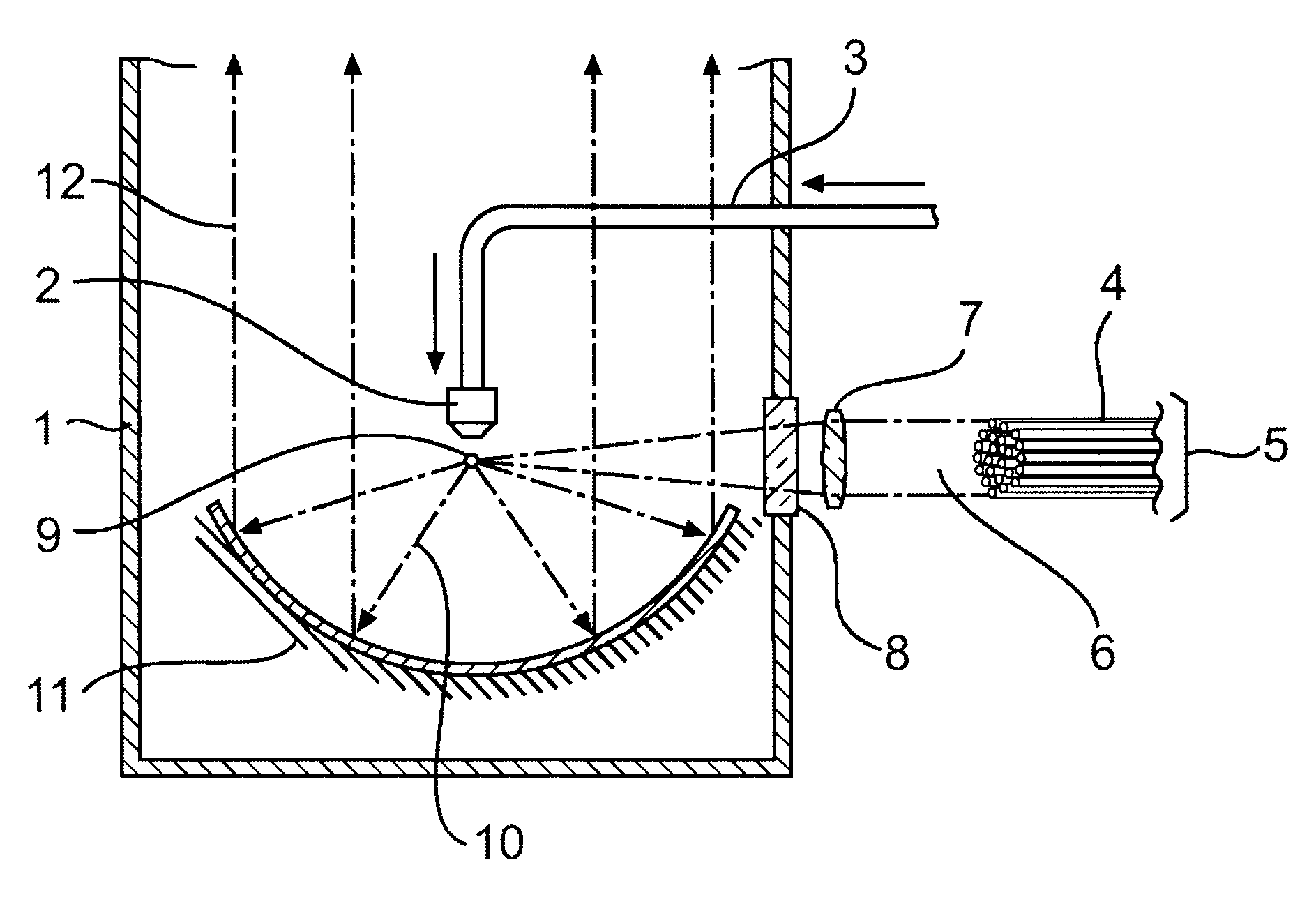
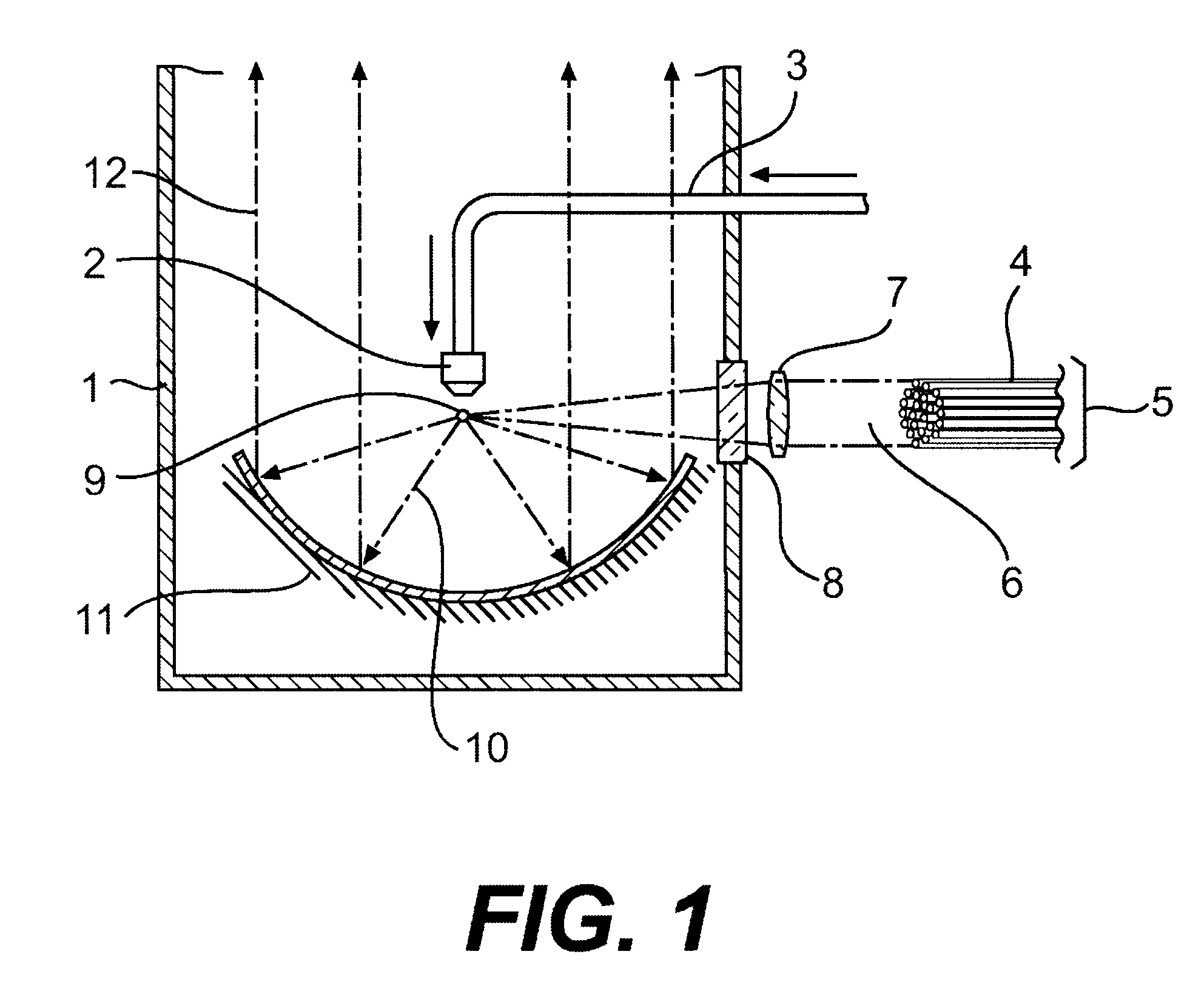
Embodiments of the present invention will be described below with reference to the drawing Figures. FIG. 1 shows a soft X-ray generating apparatus according to the present invention. In FIG. 1, a vacuum vessel 1 has a nozzle 2 therein. The nozzle 2 is positioned at the end of a gas introduction pipe. Optical fibers 4 constitutes the output terminals of fiber amplifiers and are provided as an optical fiber group 5. Laser pulse 6 emitted from the optical fibers passes through a lens 7 and an exciting laser light introduction window 8. A plasma 9 is formed and soft X-rays 10 are generated. A rotating multi-layer coat parabolic mirror 11 the soft X-rays 10 as parallel beams 12 of soft X-rays.

The nozzle 2, which jets krypton (Kr) gas, is installed inside the vacuum vessel 1, and is supplied with high-pressure krypton gas from the gas introduction pipe 3. The present apparatus has an optical fiber group 5 formed by bundling together 100 optical fibers 4 constituting the output terminals o...

second embodiment

FIG. 3 shows a soft X-ray generating apparatus according to the present invention. In FIG. 3 and the following figures, elements that are the same as elements described in connection with FIGS. 1 and 2 are labeled with the same reference numerals and symbols, and descriptions of these common elements are omitted.

In the apparatus shown in FIG. 3, the nozzle 2 jets krypton (Kr) gas into the vacuum vessel 1. High-pressure krypton gas is supplied through the gas introduction pipe 3. In this apparatus as well, one hundred optical fibers 4 are provided which are the output ends of fiber amplifiers. Micro-lenses are attached to the emission end surfaces of the optical fibers 4, so that the light beams emitted from the optical fibers 4 are parallel light beams with a diameter of approximately 0.1 mm. However, instead of being bundled into a single body, the respective optical fibers 4 are installed so that they surround the nozzle 2 from which the krypton gas is caused to jet.

The optical ax...

third embodiment

FIG. 4 shows a soft X-ray generating apparatus according to the present invention. This embodiment may be used as the light source part of an X-ray microscope. In FIG. 4, a tantalum foil, 32 is unwound from a reel 33. A reduction optical system 34, X-ray filter 35, illumination optical system 36, enlarging and imaging optical system 38, and a laser light transmitting plate 39 used to block debris are provided in this embodiment. A sample 37 is also represented.

A tape-form tantalum foil 32 with a thickness of about 15 .mu.m is installed inside the vacuum vessel 1 and is used as a target material. Laser pulse 6 emitted from an optical fiber group 5 formed by bundling together 100 optical fibers constituting the output ends of fiber amplifiers is directed onto the surface of the tantalum foil 32 by means of the reduction optical system 34. The reduction optical system 34 reduces the image at the position of the emission end surface of the optical fiber group to 1 / 10th of the original s...


PUM

PropertyMeasurementUnit
wavelengthsaaaaaaaaaa
wavelengthaaaaaaaaaa

Abstract

A high-pressure krypton gas is supplied to the interior of a vessel from a gas introduction pipe. Light emitted from an optical fiber group formed by bundling together optical fibers constituting the output ends of fiber amplifiers or fiber lasers passes through a lens and exciting laser light introduction window, and is focused on the krypton gas jetting from the tip end of the nozzle. As a result, the krypton gas is excited as a plasma and soft X-rays are generated. The soft X-rays are reflected by a rotating multi-layer coat parabolic mirror and are emitted to the outside as a parallel beam of soft X-rays. Since light from fiber amplifiers is used as exciting light, and since numerous optical fibers are bundled together to form a light source, a large quantity of soft X-rays can easily be obtained.

Description

1. Field of the InventionThe present invention relates to a soft X-ray generating apparatus and a soft X-ray lithography apparatus using this soft X-ray generating apparatus. More specifically, the present invention concerns a soft X-ray generating apparatus that can generate a large quantity of soft X-rays, and a soft X-ray lithography apparatus using this soft X-ray generating apparatus.2. Discussion of the Related ArtConventionally, in exposure equipment used in semiconductor manufacture, equipment with an exposure and transfer system has been widely used in which a photo-mask (hereafter referred to as a "mask") is irradiated by means of an irradiation optical system so that circuit patterns formed on the mask surface are projected and transferred onto a substrate such as a wafer, etc., via an image-focusing device. The substrate is coated with a resist, and the resist becomes photosensitive as a result of being exposed so that a resist pattern is obtained.The resolving power w o...

Claims


Application Information

Patent Timeline
Patent Type & Authority Patents(United States)
IPC IPC(8): G03F7/20G21K1/06G21K1/00H05G2/00
CPCB82Y10/00G03F7/70033H05G2/008G21K1/06H05G2/003G03F7/70233
Inventor KANDAKA, NORIAKIKONDO, HIROYUKIOWA, SOICHIOHTSUKI, TOMOKO
Owner NIKON CORP
Why Eureka
Try Eureka