Laser system utilizing sorbent-based gas storage and delivery system

Inactive Publication Date: 2000-09-26
ENTEGRIS INC
View PDF46 Cites 21 Cited by
  • Summary
  • Abstract
  • Description
  • Claims
  • Application Information

AI Technical Summary

Benefits of technology

(I) to provide, exteriorly of said storage and dispensing vessel, a pressure below said interior pressure, to effect desorption of fluid from the sorbent material, and flow of desorbed fluid from the vessel through the dispensing assembl

Problems solved by technology

The method disclosed in the Knoilmueller patent is disadvantageous in that it requires the provision of heating means for the zeolite material, which must be constructed and arranged to heat the zeolite to sufficient temperature to desorb the previously sorbed arsine from the zeolite in the desired quantity.
The use of a heating jacket or other means exterior to the vessel holding the arsine-bearing zeolite is problematic in that the vessel typically has a significant heat capacity, and therefore introduces a significant lag time to the dispensing operation.
Further, heating of arsine causes it to decompose, resulting in the formation of hydrogen gas, which introduces an explosive hazard into the process system.
Additionally, such thermally-mediated decomposition of arsine effects substantial increase in gas pressure in the process system, which may be extremely disadvantageous from the standpoint of system life and operating efficiency.
The provision of interiorly disposed heating coil or other heating elements in the zeolite bed itself is problematic since it is difficult with such means to uniformly heat the zeolite bed to achieve the desired uniformity of arsine gas release.
The use of heated carrier gas streams passed through the bed of zeolite in its

Method used


Image

  • Laser system utilizing sorbent-based gas storage and delivery system
  • Laser system utilizing sorbent-based gas storage and delivery system
  • Laser system utilizing sorbent-based gas storage and delivery system

Examples


Embodiment Construction

The disclosures of the following U.S. patents and U.S. patent applications are hereby incorporated herein by reference in their entirety:

U.S. Pat. No. 5,935,305 issued Aug. 10, 1999;

U.S. Pat. No. 5,518,528 issued May 21, 1996;

U.S. Pat. No. 5,704,965 issued Jan. 6, 1998;

U.S. Pat. No. 5,704,967 issued Jan. 6, 1998;

U.S. Pat. No. 5,707,424 issued Jan. 13, 1998;

U.S. Pat. No. 5,761,910 issued Jun. 9, 1998; and

U.S. patent application Ser. No. 09 / 002,278 filed Dec. 31, 1997.

In the ensuing disclosure, the invention will be described with reference to a gas as the sorbate fluid, however, it will be recognized that the invention is broadly applicable to liquids, gases, vapors, and multiphase fluids, and contemplates storage and dispensing of fluid mixtures as well as single component fluids.

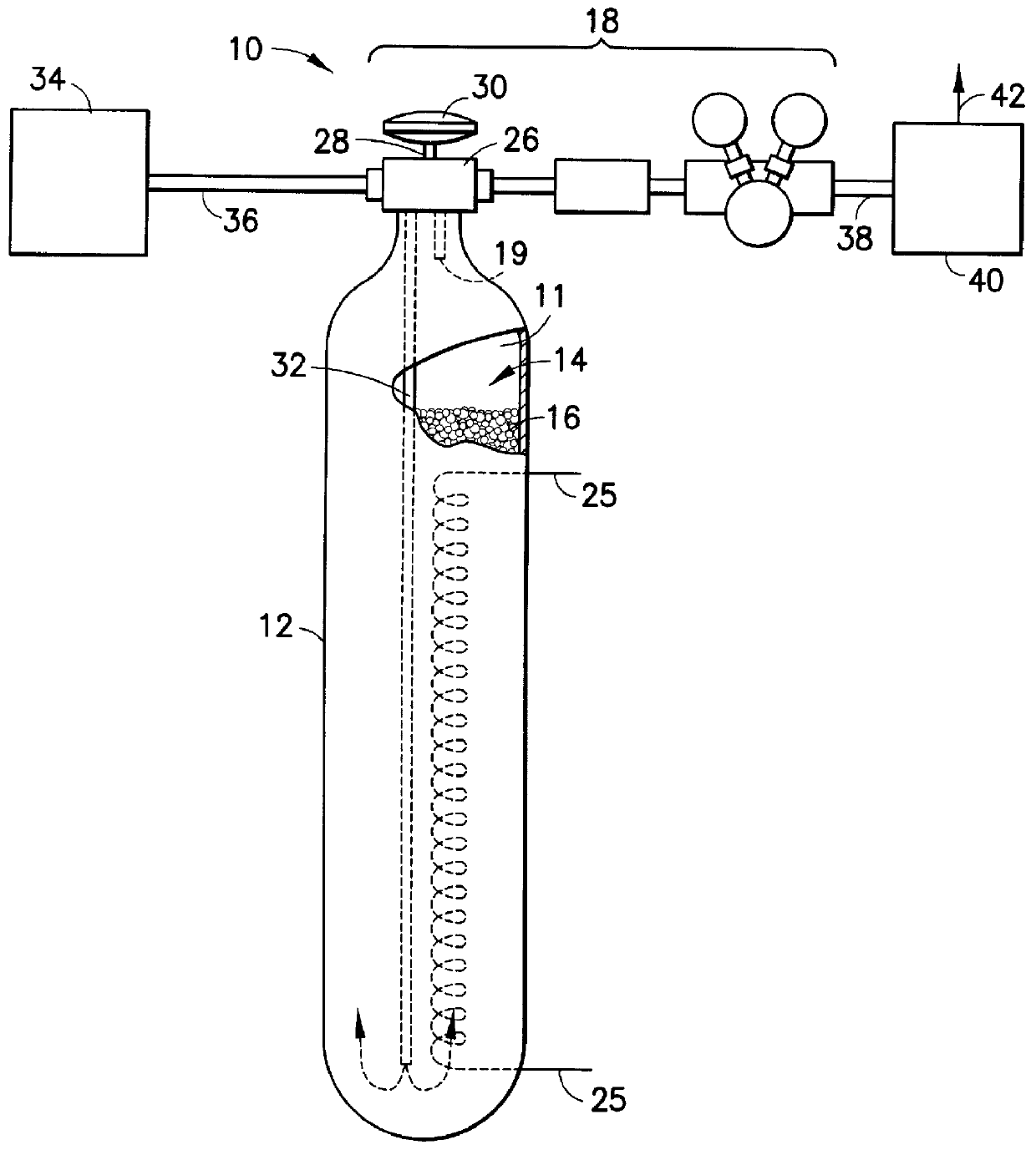
Referring now to the drawings, FIG. 1 is a schematic representation of a storage and dispensing system 10 comprising storage and dispensing vessel 12 which may be usefully employed for supplying laser gas t...


PUM

PropertyMeasurementUnit
Pressureaaaaaaaaaa
Flow rateaaaaaaaaaa
Concentrationaaaaaaaaaa

Abstract

A laser system utilizing a fluid as the excitatory medium for stimulated light emission, wherein the fluid is supplied from a sorbent-based fluid storage and dispensing system coupled in fluid-supplying relationship with the laser apparatus. The laser may be an excimer laser utilizing as the laser working fluid a rare gas halide compound such as fluorides and/or chlorides of krypton, xenon and argon, as well as fluorine and/or chlorine per se. The laser system may alternatively be a far infrared gas laser utilizing a gas such as CO2, N2O, CD3OD, CH3OD, CH3OH, CH3NH2, C2H2F2, HCOOH, CD3I, CH3F, and C13H3F. Laser systems of the present invention may be utilized in applications such as materials processing, measurement and inspection, reading, writing, and recording of information, holography, communications, displays, spectroscopy and analytical chemistry, remote sensing, surveying, marking, and alignment, surgical and medical applications, plasma diagnostics, laser weaponry, laser-induced nuclear fusion, isotope enrichment and atomic physics.

Description

1. Field of the InventionThis invention relates generally to storage and dispensing systems for the selective dispensing of fluids from a vessel in which the fluid component(s) are sorptively retained by a solid sorbent medium, and are desorptively released from the sorbent medium in the dispensing operation. More particularly, the present invention relates to a laser system utilizing such a storage and dispensing system for gas supply to the laser as the excited medium for generating laser output.2. Description of the Related ArtIn a wide variety of industrial processes and applications, there is a need for a reliable source of process fluid(s) which is compact, portable, and available to supply the fluid(s) on demand. Such processes and applications include semiconductor manufacturing, ion implantation, manufacture of flat panel displays, medical treatment, water treatment, emergency breathing equipment, welding operations, space-based applications involving delivery of liquids an...

Claims


Application Information

Patent Timeline
IPC IPC(8): F17C11/00B01D53/04B01J4/02B01J20/18B01J20/20
CPCB01D53/0407B01J20/20F17C11/00F17C11/007B01D2253/308B01D2259/4525F17C2205/0338F17C2205/0391Y02C10/08Y02C20/10Y10S95/902Y02C20/40
Inventor BRANDES, GEORGE R.TOM, GLENN M.MCMANUS, JAMES V.
Owner ENTEGRIS INC
Why Eureka
Try Eureka