
Executing multiple debug instructions

a debug instruction and instruction technology, applied in the field of data processing systems, can solve the problems of general slowness of serial scan chains for large numbers of instructions and data values

Inactive Publication Date: 2002-01-29
ARM LTD
View PDF6 Cites 52 Cited by
  • Summary
  • Abstract
  • Description
  • Claims
  • Application Information

AI Technical Summary

Benefits of technology

The implementation of the present technique is eased in embodiments in which the data transfer register is an addressable register that may be specified as an operand within one or more data processing instructions. In this way the degree of change required in the rest of the system to carry the present technique can be reduced.
In order to reduce potential data conflicts due to the main processor and the debug logic both trying to access the data transfer register at the same time, in preferred embodiments the data transfer register is in the form of two registers forming a bidirectional communications channel.
In preferred embodiments of the invention said data transfer register includes an instruction complete flag settable by said main processor for indicating that said data processing instruction has completed an execution iteration. In this way external debug circuitry may poll this flag after it has issued an instruction to determine when the instruction has completed and that it write more data to or read more data from the data transfer register. The scan chain controller may already be set to have the second serial scan selected as the active scan chain and so the polling can be quickly performed and a subsequent transfer will not require a change of active scan chain to be made.
As a way of increasing efficiency further, in preferred embodiments said second serial scan chain is operable to output bits of a data value to be transferred out of said data transfer register at the same time as storing bits of a data value to be transferred into said data transfer register. In this way each serial scan chain bit shift both loads in one bit of data and outputs one bit of data in a manner that reduces the time needed for transferring words of data into and out of the system.

Problems solved by technology

It is generally slow to scan in large numbers of instructions and data values via serial scan chains.

Method used


Image

  • Executing multiple debug instructions
  • Executing multiple debug instructions
  • Executing multiple debug instructions

Examples


Embodiment Construction

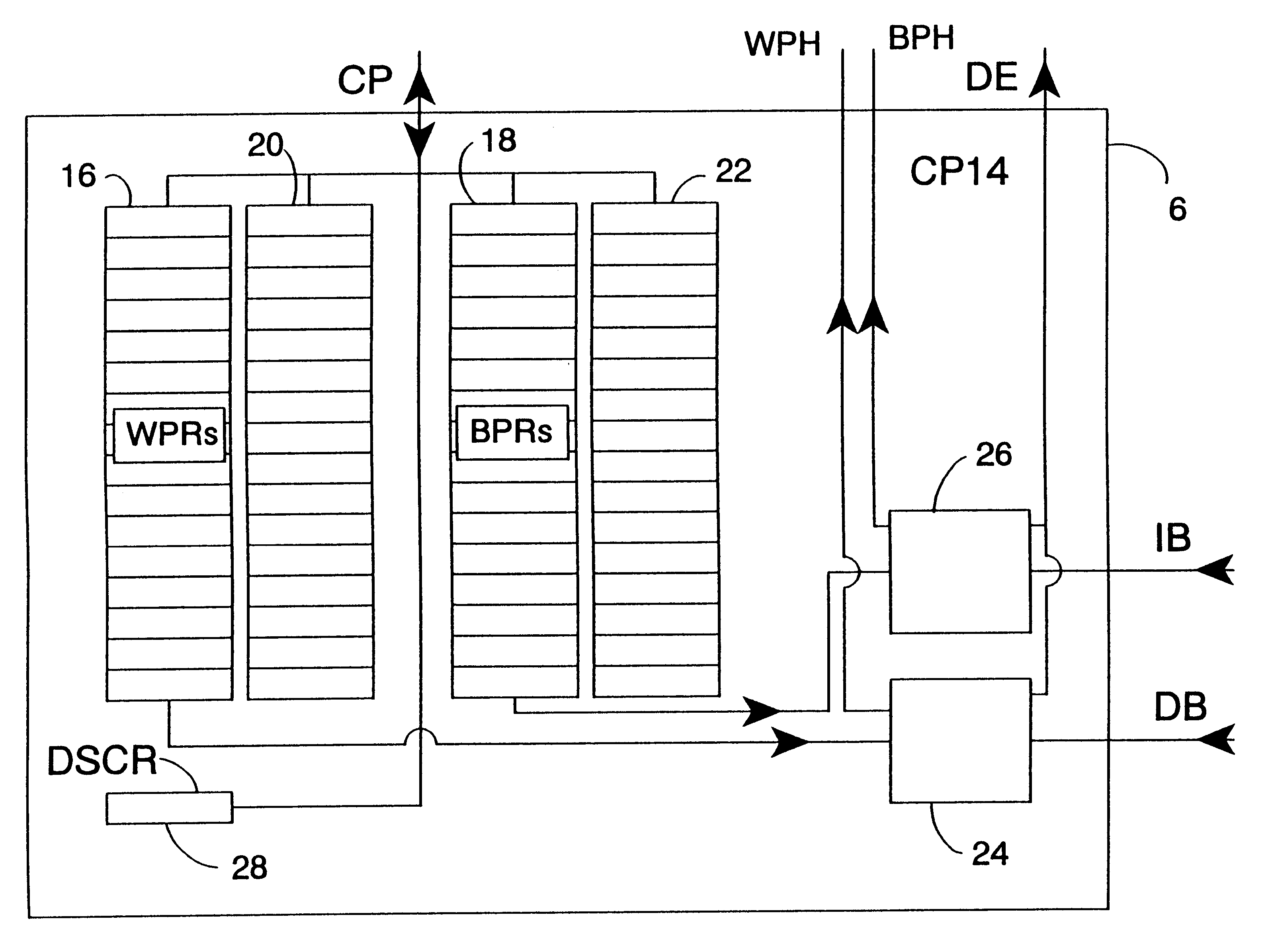
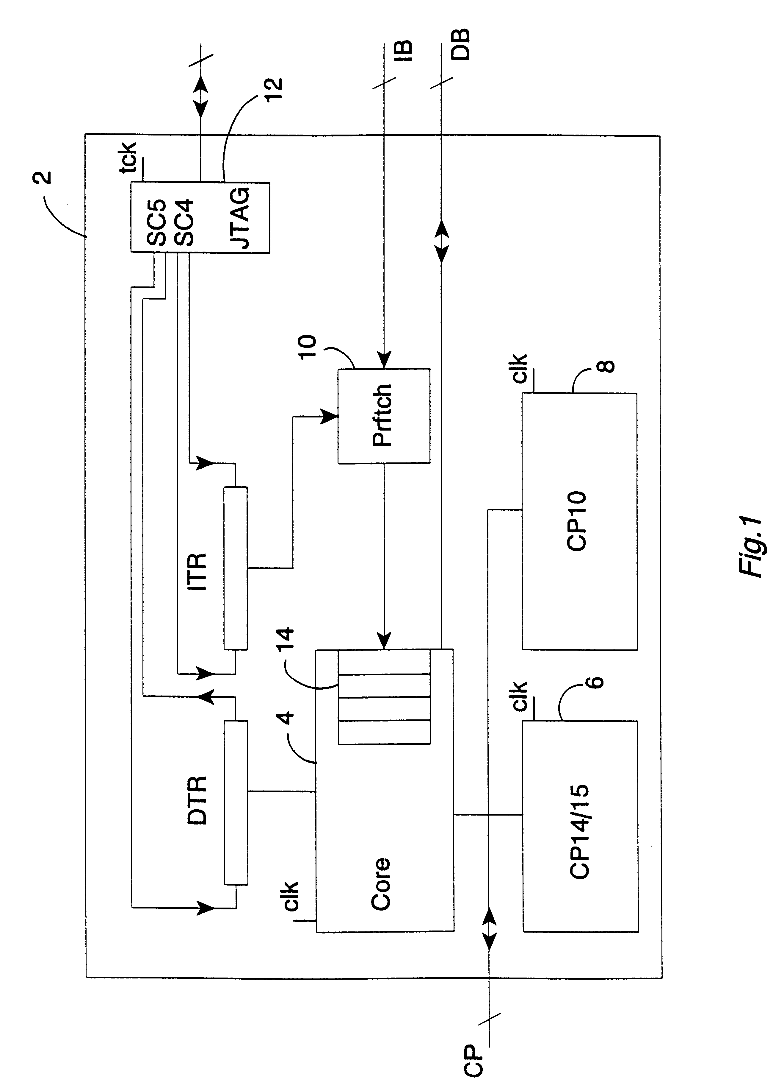
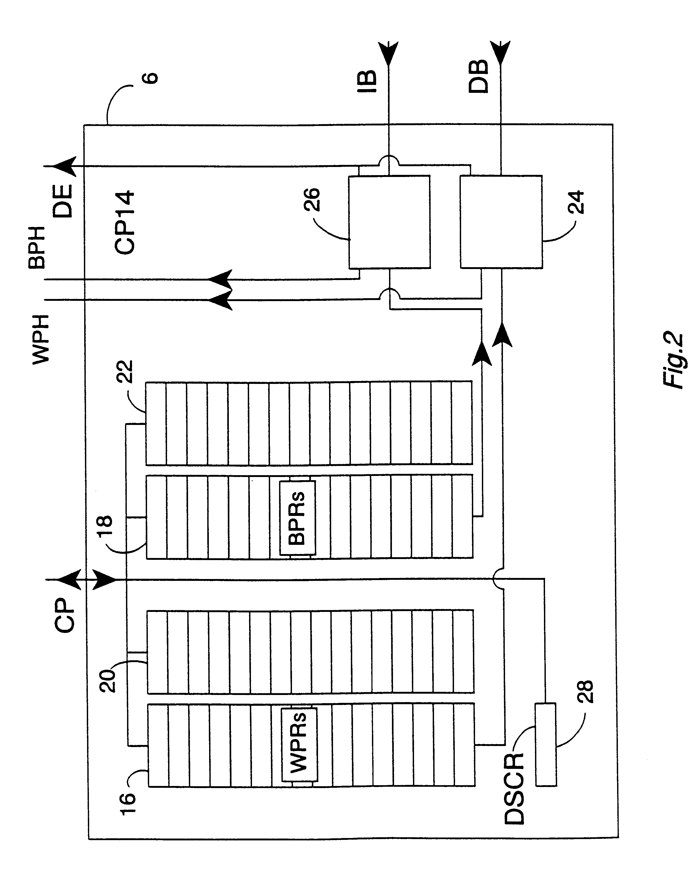
FIG. 1 shows a data processing system 2 that includes a main processor 4, a debug coprocessor (and system coprocessor) 6 and a floating point unit coprocessor 8. The main processor 4 is coupled via a coprocessor interface in the form of a coprocessor bus CP to the debug coprocessor 6 and the floating point unit coprocessor 8. The form of this coprocessor bus CP is substantially the same as a standard coprocessor bus, such as the ARM coprocessor bus (as used with microprocessors produced by ARM Limited of Cambridge, England).

The main processor 4 is coupled to a data bus DB and via a prefetch unit 10 to an instruction bus IB. The data bus DB and the instruction bus IB both include address portions that are monitored by the debug coprocessor 6 to identify breakpoints and watchpoints respectively.

The main processor 4, the debug coprocessor 6 and the floating point unit coprocessor 8 are all driven by a common main processor clock signal clk at a main processor clock frequency. A scan ch...


PUM


Abstract

Apparatus for processing data is provided, said apparatus comprising: a main processor 4; an instruction transfer register ITR for holding a data processing instruction and accessible via a first serial scan chain SC4; a data transfer register DTR for holding a data value and accessible via a second serial scan chain SC5; debug logic 6, 12 for controlling said main processor 4, said instruction transfer register ITR and said data transfer register DTR such that a data processing instruction held within said instruction transfer register ITR is passed a plurality of times to said main processor 4 for execution upon a sequence of data values scanned into or from said data transfer register via said second serial scan chain. In this way operational speed of the debug mode is increased since the data processing instruction only needs to be transferred once.

Description

1. Field of the InventionThis invention relates to the field of data processing systems. More particularly, this invention relates to data processing systems including debug mechanisms where it is desired to execute multiple debug instructions.2. Description of the Prior ArtIt is known to provide data processing systems with debug mechanisms for assisting in the debugging of hardware and software. One known technique is to use JTAG serial scan chains to scan in instructions and data to be applied to the system being debugged. It is generally slow to scan in large numbers of instructions and data values via serial scan chains.Viewed from one aspect the present invention provides an apparatus for processing data, said apparatus comprising:a main processor;an instruction transfer register for holding a data processing instruction and accessible via a first serial scan chain;a data transfer register for holding a data value and accessible via a second serial scan chain;debug logic for c...

Claims


Application Information

Patent Timeline
Patent Type & Authority Patents(United States)
IPC IPC(8): G01R31/28G01R31/3185G06F11/22
CPCG01R31/318555G01R31/318569G01R31/318566
Inventor JAGGAR, DAVID VIVIANHOHL, WILLIAM ADAMHALL, JAMES STROMAN
Owner ARM LTD
Learn More