Process and apparatus for providing a film with a gradient

a technology of gradient and process, applied in the field of glazing panels, can solve the problems of color not very desirable for aesthetic reasons, appearance in reflection, color may not be highly appreciated,

Inactive Publication Date: 2002-03-12
SAINT-GOBAIN GLASS FRANCE
View PDF37 Cites 71 Cited by
  • Summary
  • Abstract
  • Description
  • Claims
  • Application Information

AI Technical Summary

Benefits of technology

Thus, the lowest refractive index in this index gradient is preferably between 1.45 and 1.60 while the highest refractive index is preferably between 1.70 and 2.35. The difference between the lowest index and the highest index is in fact to be chosen to be relatively large in order to obtain the advantageous effects of the invention in an optimal way.
A preferred method of producing this index gradient consists in decreasing the refractive index of the intermediate film from a value close to the refractive index of the functional film to a value close to the refractive index of the substrate.
As regards the geometric thickness of the intermediate film, this is preferably chosen to be between 30 and 120 nm, for example between 40 and 120 nm, especially between 45 and 90 nm, or between 50 and 100 nm. The thickness must in fact be sufficient to be able to actually produce the index gradient.
There are various possible ways of creating this index gradient. The simplest is to obtain it by progressively varying the chemical composition of the intermediate film throughout its thickness, especially by mixing at least two components having different refractive indices, the amount of component or mixture of components having the highest index (or indices) gradually decreasing through its thickness. The choice of these components may, for example, be as follows: for the low-index component silicon oxide, silicon oxynitride or silicon oxycarbide is suitable and for the higher-index components tin oxide, titanium oxide, zirconium oxide, aluminium oxide, magnesium oxide, vanadium oxide, silicon oxycarbide or silicon nitride, or a mixture of at least two of these compounds, is suitable.
This gradient may be obtained using a vacuum technique or by pyrolysis, most especially by pyrolysis in the gas phase. To do this, a particularly suitable gas feed nozzle has been designed according to the invention. This nozzle is placed above the glass, transversely to its running direction, when it is in the form of a ribbon of float glass, and is preferably placed within the actual chamber of the float bath. It includes a first upstream heel-piece, a second upstream heel-piece, a central profiled block and a downstream heel-piece. A first precursor-gas injection slot is made between the two upstream heel-pieces and. a second injection slot is made between the central block and the downstream heel-piece. A slot for evacuating the unreacted gaseous effluent is provided between the central profiled block and the downstream heel-piece. Thus, all these slots and the lower faces of the heel-pieces and of the central block guide the gas streams supplying the two injection slots along the glass in a deposition zone, with a flow path having approximately the shape of a U. In order to create partial and progressive mixing between these two gas streams in the deposition zone, and thus to create the desired composition gradient, certain geometric parameters of the nozzle are adjusted. The two important parameters are, on the one hand, the distance 1 between the injection slots and, on the other hand, the relative configurations of the two upstream heel-pieces and the central block. Consequently, in order to achieve the desired effect, the preferred embodiment consists in the lower face of the central block being at a higher level than that of the second upstream heel-piece which is adjacent to it and the lower face of this second upstream heel-piece itself being at a higher level than that of the first upstream heel-piece.
With regard to the distance 1 between the two injection slots, it is advantageous to choose it to be at most equal to 3 / 4 of the total length of the deposition zone, especially approximately 1 / 4 to 2 / 3 of the said length.

Problems solved by technology

A thin film having such thicknesses gives the substrate which it covers an appearance in reflection, especially a coloration, which may not be highly appreciated from an aesthetic standpoint.
Thus arises the problem of the appearance in reflection, most particularly of the residual coloration obtained, of the substrate coated in this way.
On the other hand, it has been observed that a film of the same kind but this time having a thickness of 360 nm, and therefore a film having superior performance, gives the same substrate an appearance in reflection, "on the film side", in the greens / purples, which colour is not very desirable for aesthetic reasons.
These variations are caused, in an interferential way, by irregularity in the thickness of the films and most particularly in the thickness of the functional film.

Method used


Image

  • Process and apparatus for providing a film with a gradient
  • Process and apparatus for providing a film with a gradient
  • Process and apparatus for providing a film with a gradient

Examples


examples 1 to 7

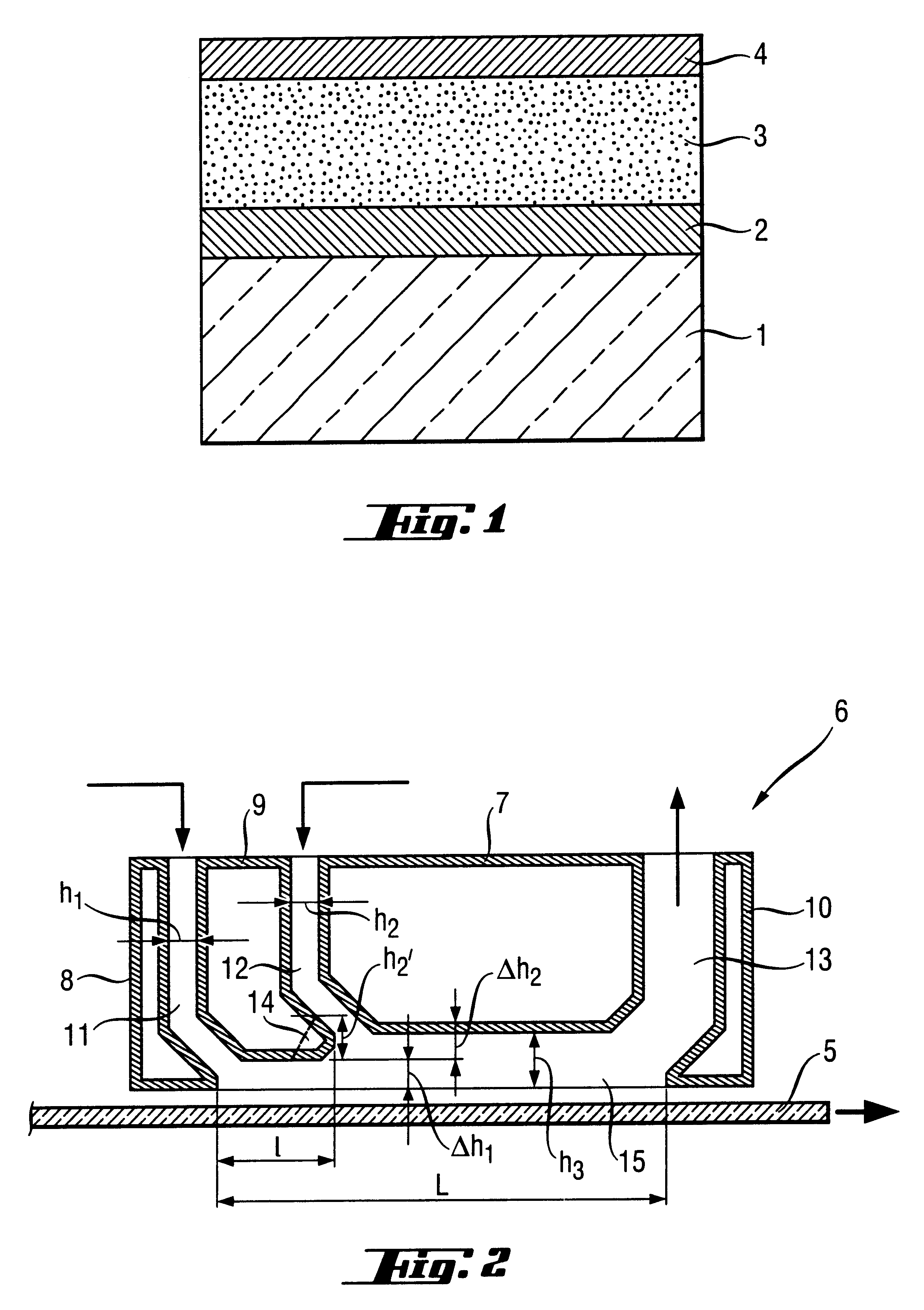
are produced according to the invention and are the result of mathematical modelling. They model, in accordance with FIG. 1, a substrate 1 made of clear soda-lime silicate glass 4 mm in thickness. This is coated with an F:SnO.sub.2 -based low-emissivity film 3 obtained in a known way by powder pyrolysis using DBTF, as described in the aforementioned patents, and then with an external film 4 based on a mixed silicon and aluminium oxide, also with fluorine, this film also being obtained in a known way by CVD using tetraorthosilicate TEOS, aluminium hexafluoroacetylacetonate and oxygen, in accordance with the teaching of the French application FR-94 / 13911 published under the number FR-2 727 107 corresponding to the patent EP-0,712,815. Sandwiched between the substrate 1 and the functional film 3 is an intermediate film 2 having a decreasing refractive index gradient, that is to say the refractive index of which progressively decreases through its thickness from its interface with the g...

examples 10 to 12

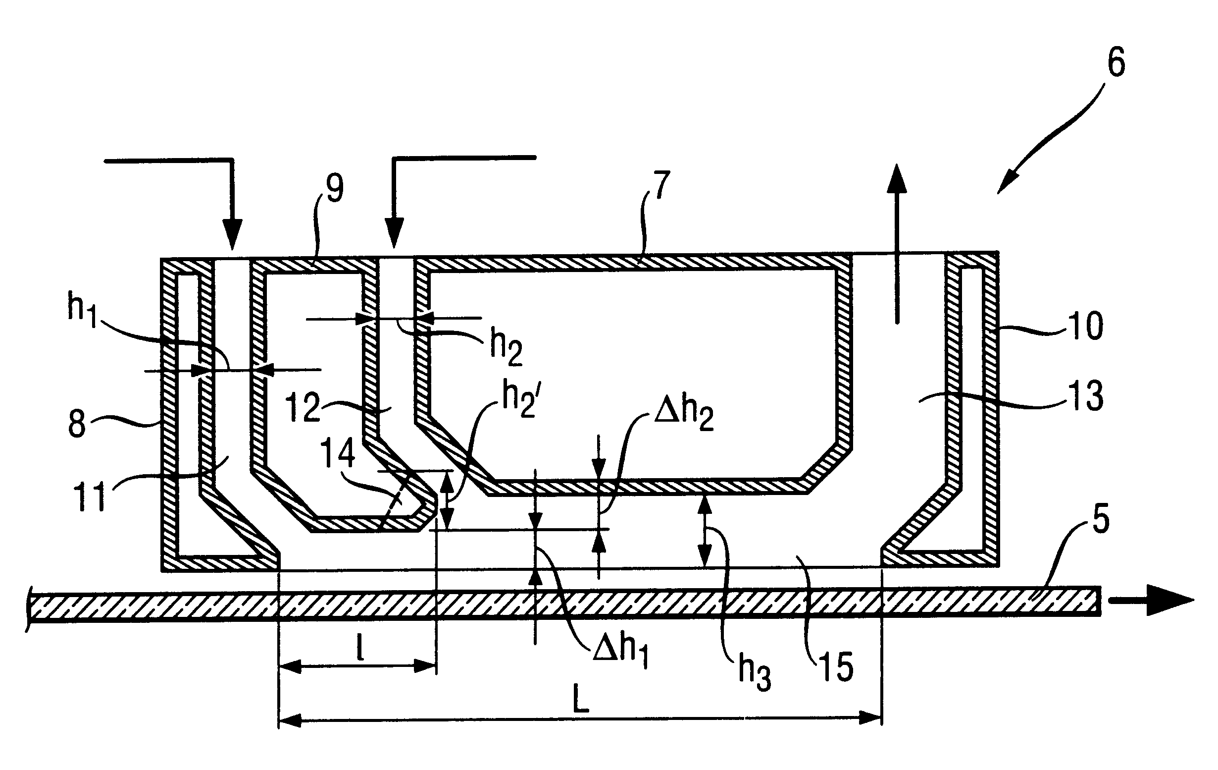
These examples were produced using the nozzle described above, by depositing, on a substrate of soda-lime silicate glass 4 mm thick, SnO.sub.2 / SiO.sub.2 -based films whose refractive index decreases progressively on going away from the glass.

The first slot 11 is supplied with dibutyltin diacetate DBTA and the second slot 12 with TEOS.

Table 4 below-indicates, for these three examples, the ratio R of the TEOS and DETA volume flowrates, the thickness t in nm of the film and the values, ri (min) and ri (max), according to the conventions adopted in Table 1:

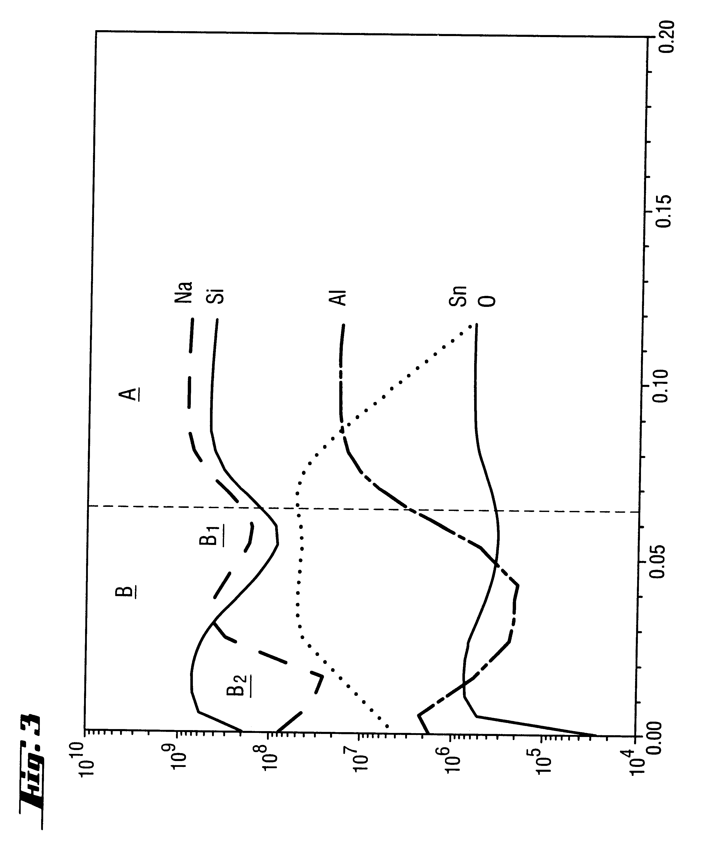
These three substrates thus coated were analyzed by SIMS (Secondary Ion Mass Spectroscopy): FIGS. 3, 4 and 5 correspond respectively to the films according to Examples 10, 11 and 12. The graphs represent, as abscissae, the depth of the analysis in micrometers and, as ordinates, the number of counts per second on a logarithmic scale.

Only the elements which are more particularly relevant to the invention are depicted in these three gra...


PUM

PropertyMeasurementUnit
thicknessaaaaaaaaaa
thicknessaaaaaaaaaa
thicknessaaaaaaaaaa

Abstract

The subject of the invention is a glazing panel comprising a transparent substrate (1) especially one made of glass, provided with at least one functional, conductive and / or low-emissivity, transparent thin film (3). In order to improve the optical and especially the calorimetric appearance of the glazing panel, at least one intermediate film (2) is placed between the substrate (1) and the functional film (3), this at least one intermediate film having a refractive index gradient decreasing through its thickness.The invention also relates to the device intended for manufacturing this type of glazing panel.

Description

BACKGYOUND OF THE INVENTIONThe invention relates to a glazing panel comprising a glass substrate provided with a functional thin film, the latter exhibiting properties of transparency, electrical conductivity and / or low emissivity.It also relates to the processes for obtaining such a glazing panel, in particular by means of pyrolysis or of techniques-using a vacuum.This type of functional film is most particularly applicable for glazing panels intended for buildings: a glass substrate, coated with a low-emissivity film, makes it possible to reduce the emission in the far infrared through the glazing panel, of which it forms part, from inside the premises to the outside. By reducing the energy losses due partly to this radiation leakage, the comfort of the inhabitants is appreciably improved, especially in winter. The substrate thus coated and then combined with another substrate via a layer of gas, the low-emissivity film lying as face 3 (counting from the outermost face), constitut...

Claims


Application Information

Patent Timeline
Patent Type & Authority Patents(United States)
IPC IPC(8): C03C17/34C23C16/02C23C16/453C23C16/44
CPCC03C17/3417C03C17/3435C03C17/3441C23C16/029C23C16/453Y10T428/265Y10T428/24942C03C2217/91
Inventor BOIRE, PHILIPPEZAGDOUN, GEORGES
Owner SAINT-GOBAIN GLASS FRANCE
Why Eureka
Try Eureka