System and method for controlled delivery of liquefied gases from a bulk source

a gas delivery system and liquefied gas technology, applied in the direction of container discharging methods, mechanical devices, non-pressure vessels, etc., can solve the problems of harmful to the components of the gas delivery system, deleterious effect on the process and apparatus, and heat of evaporation utilized that cannot be compensated by external hea

Inactive Publication Date: 2002-04-02
LAIR LIQUIDE SA POUR LETUDE & LEXPLOITATION DES PROCEDES GEORGES CLAUDE +1
View PDF10 Cites 56 Cited by
  • Summary
  • Abstract
  • Description
  • Claims
  • Application Information

AI Technical Summary

Problems solved by technology

However, one of the difficulties associated with these type systems is maintaining the phase equilibrium properties necessary to deliver the gas phase at a desired flow rate.
This phenomenon arises from the fact that under practical conditions the heat of evaporation utilized is not compensated by external heat.
Further, withdrawal of vapor phase ESG at a high flow rate may entrain liquid droplets of the gas, thereby having a deleterious effect on the process and apparatus.
Thus, condensation of these materials in the gas delivery system can lead to corrosion, which is harmful to the components of the gas delivery system.
Moreover, the corrosion products can lead to contamination of the highly pure process gases.
This contamination can have deleterious effects on the processes being run, and ultimately on the manufactured semiconductor devices.
The presence of liquid in the gas delivery system has also been determined to lead to inaccuracies in flow control.
That is, the accumulation of liquid in various flow control devices can cause flow rate and pressure control problems as well as component failure, leading to misprocessing.
One example of such behavior is the swelling of a valve seat by liquid chlorine, which causes the valve to become permanently closed.
Such failure can necessitate shutdown of the process during replacement of the failed parts and subsequent leak checking.
Extensive process downtime can result.
In addition, since the temperature outside the bulk vessel is not representative of the conditions of the product to be distributed therefrom, energy transfer means are provided in an area that holds liquid phase gas.

Method used


Image

  • System and method for controlled delivery of liquefied gases from a bulk source
  • System and method for controlled delivery of liquefied gases from a bulk source

Examples


Embodiment Construction

The invention provides for maintaining controlled conditions of the gas-liquid phase equilibrium in order to deliver gases from a delivery vessel holding a bulk quantity of the gas in liquefied state at a desired flow rate.

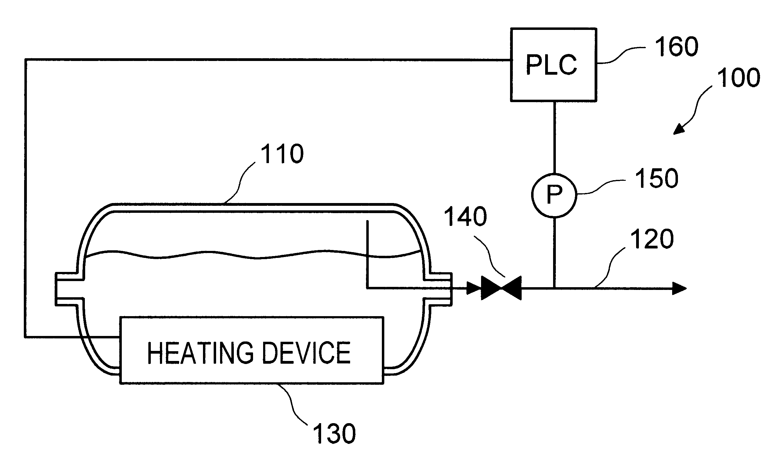
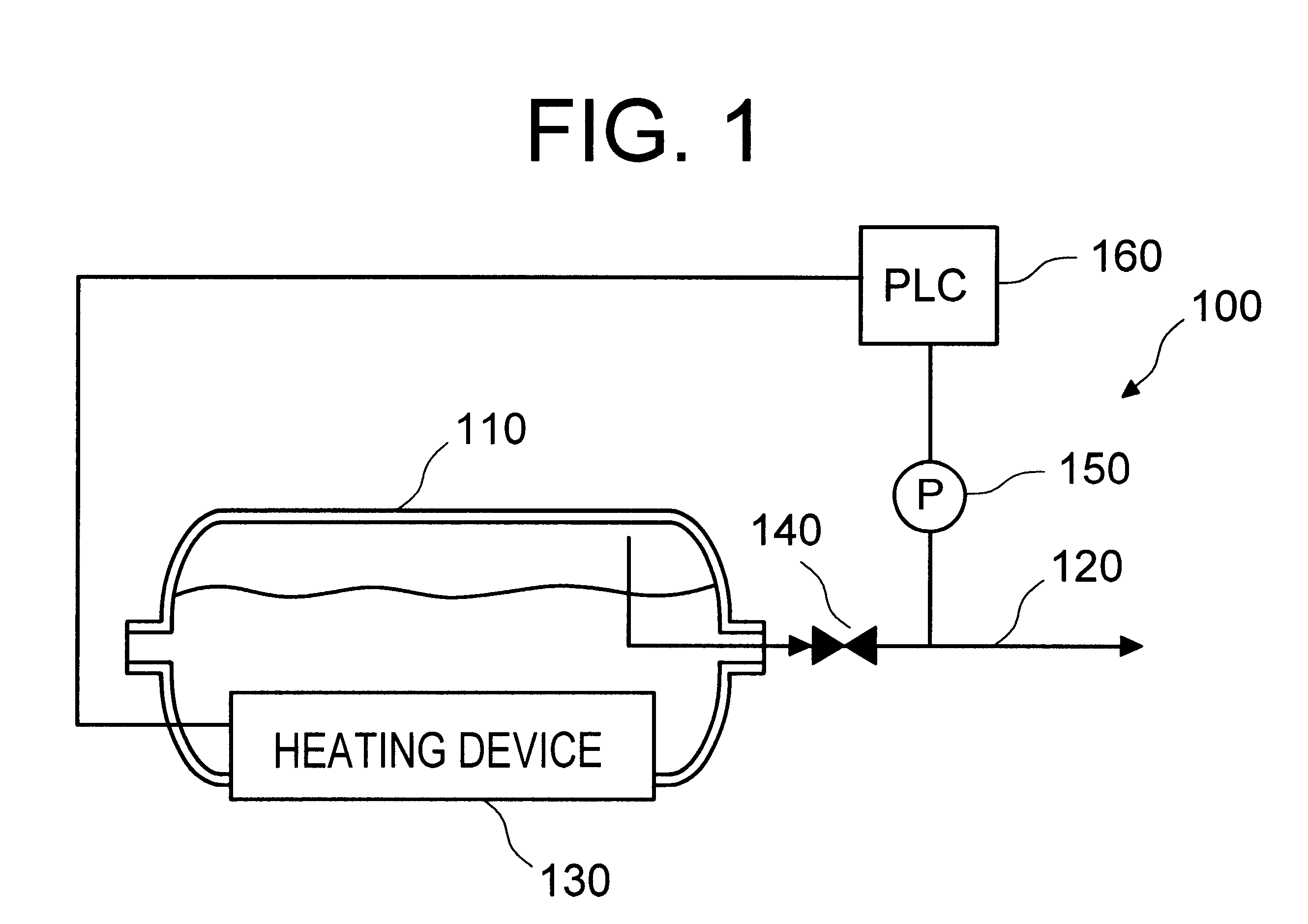
The invention will be described with reference to the FIGURE of the Drawing, which illustrates a schematic system 100 for delivery of a gas from a bulk source in accordance with one exemplary aspect of the invention. It is noted, however, that specific configurations will generally depend on factors such as cost, safety requirements and the like.

A chemical, such as a liquefied electronic specialty gas (ESG), is stored in bulk vessel 110 under its own vapor pressure. The bulk vessel can be constructed from a material such as type 304 and 316 stainless steel, Hastelloy, nickel or a coated metal (e.g., a zirconium-coated carbon) which is strictly non-reactive with the ESG and can withstand both a vacuum and high pressures. The specific material contained within the b...


PUM


Abstract

Provided is a novel system and method for delivery of gas from a liquefied state. The system includes (a) a delivery vessel holding a bulk quantity of liquefied gas therein; (b) a heat exchanger disposed on the delivery vessel to provide or remove energy from the liquefied gas only; and (c) a pressure controller for monitoring and adjusting the energy delivered to the vessel. The system and method allow for controlled delivery of liquefied gas from a delivery vessel at a predetermined flow rate. Particular applicability is found in the delivery of gases to semiconductor process tools.

Description

1. Field of the InventionThe present invention relates to a system and method for controlled delivery of a gas from a liquefied state. In particular, the invention relates to a system and method for delivery of a gas from a bulk source.2. Description of Related ArtIn the semiconductor manufacturing industry, high purity gases stored in bulk delivery vessels are supplied to process tools for carrying out various semiconductor fabrication processes. Examples of such processes include diffusion, chemical vapor deposition (CVD), etching, sputtering and ion implantation.Of the numerous gases utilized in the semiconductor manufacturing processes, many are stored in bulk delivery vessels in a liquefied state. A partial list of chemicals stored in this manner, and the pressures under which they are typically stored, is provided below in Table 1:The primary purpose of the bulk delivery vessel and system is to store the above-listed electronic specialty gases (ESG) and provide a safe vehicle ...

Claims


Application Information

Patent Timeline
Patent Type & Authority Patents(United States)
IPC IPC(8): F17C9/00F17C9/02F17C7/04F17C13/00
CPCF17C7/04F17C9/02F17C2221/05F17C2223/013Y02E60/321F17C2227/0369F17C2250/043F17C2250/0631F17C2270/0518F17C2225/0123Y02E60/32
Inventor UDISCHAS, RICHARD J.JURCIK, BENJAMIN J.WANG, HWA-CHIIRWIN, ROBERT G.
Owner LAIR LIQUIDE SA POUR LETUDE & LEXPLOITATION DES PROCEDES GEORGES CLAUDE
Why Eureka
Try Eureka