Unfortunately, this approach still produces a
lag between the time the
amplifier increases the drive voltage / current and the corresponding stabilization of the voltage at the CPU core.
While it may be true that in many analog integrated circuits it is impossible to predict the future demand requirements of a given complex load, this is not the case with
digital circuitry, because in general these systems are clocked by a known
system clock generator, making their behavior temporally deterministic.
This reactive approach can never have the bandwidth necessary to react instantaneously to
peak current demands by the load, and as such is inferior to a proactive approach to regulation.
The drawback with this design approach is that the PWM or frequency converter in the switching regulator may not be able to respond fast enough to adequately regulate the output voltage in periods of peak power loading demands.
These configurations emit a significant amount of EMI that must be either filtered or shielded from the surrounding environment.
These preventative measures not only cost money, but also increase the weight of portable equipment.
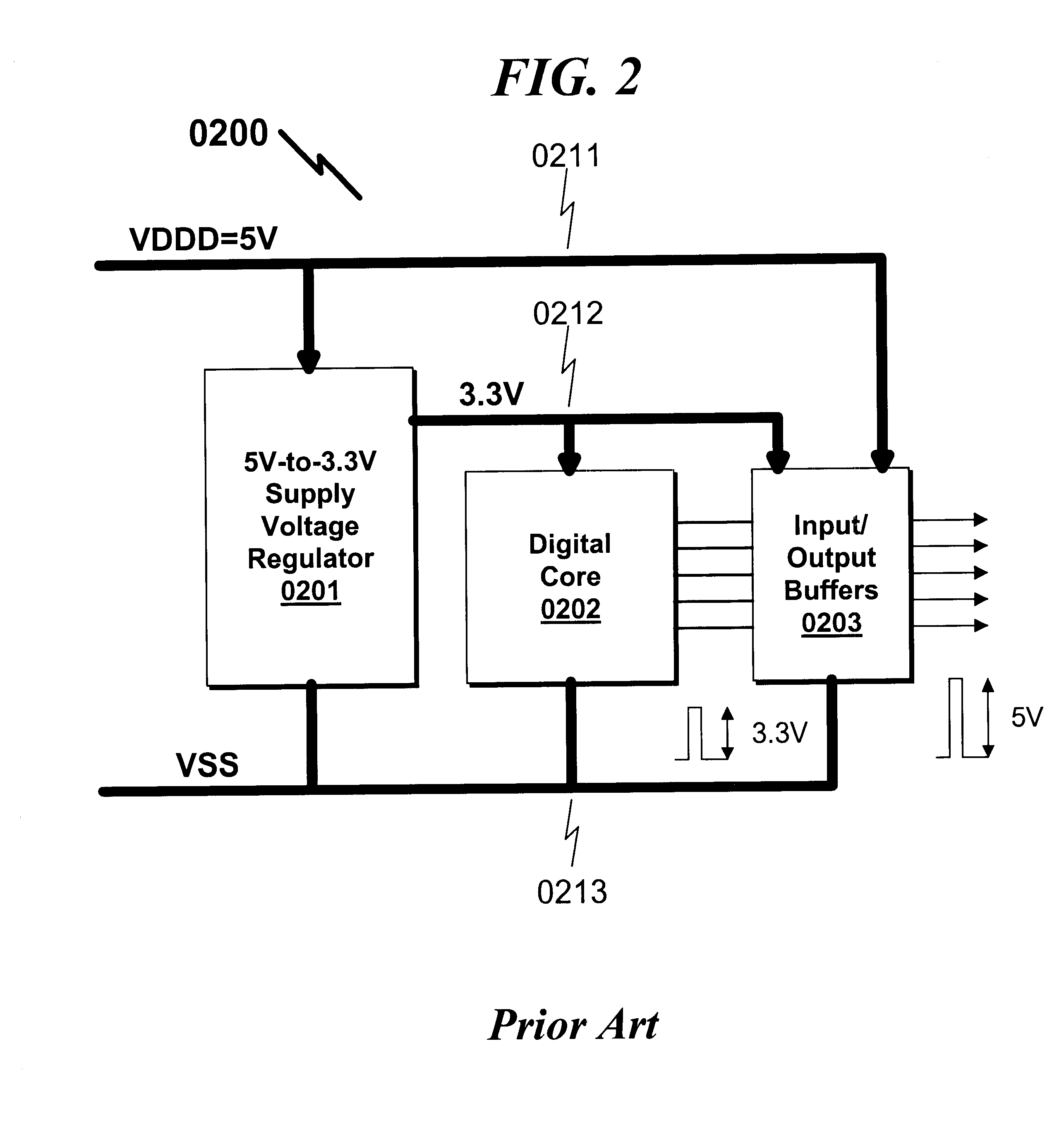
It should also be noted that due to the high
clock frequencies present in modern
digital integrated circuits, there would be significant problems in routing this clocking information outside the
chip to feed to a discrete regulator circuit.
Even if such a
system could be constructed, the EMI that would be generated by such a system would make it prohibitive from a regulatory sense, and extremely expensive to shield from an economic perspective.
Therefore, with current
system construction methods, this would not be a practical alternative.
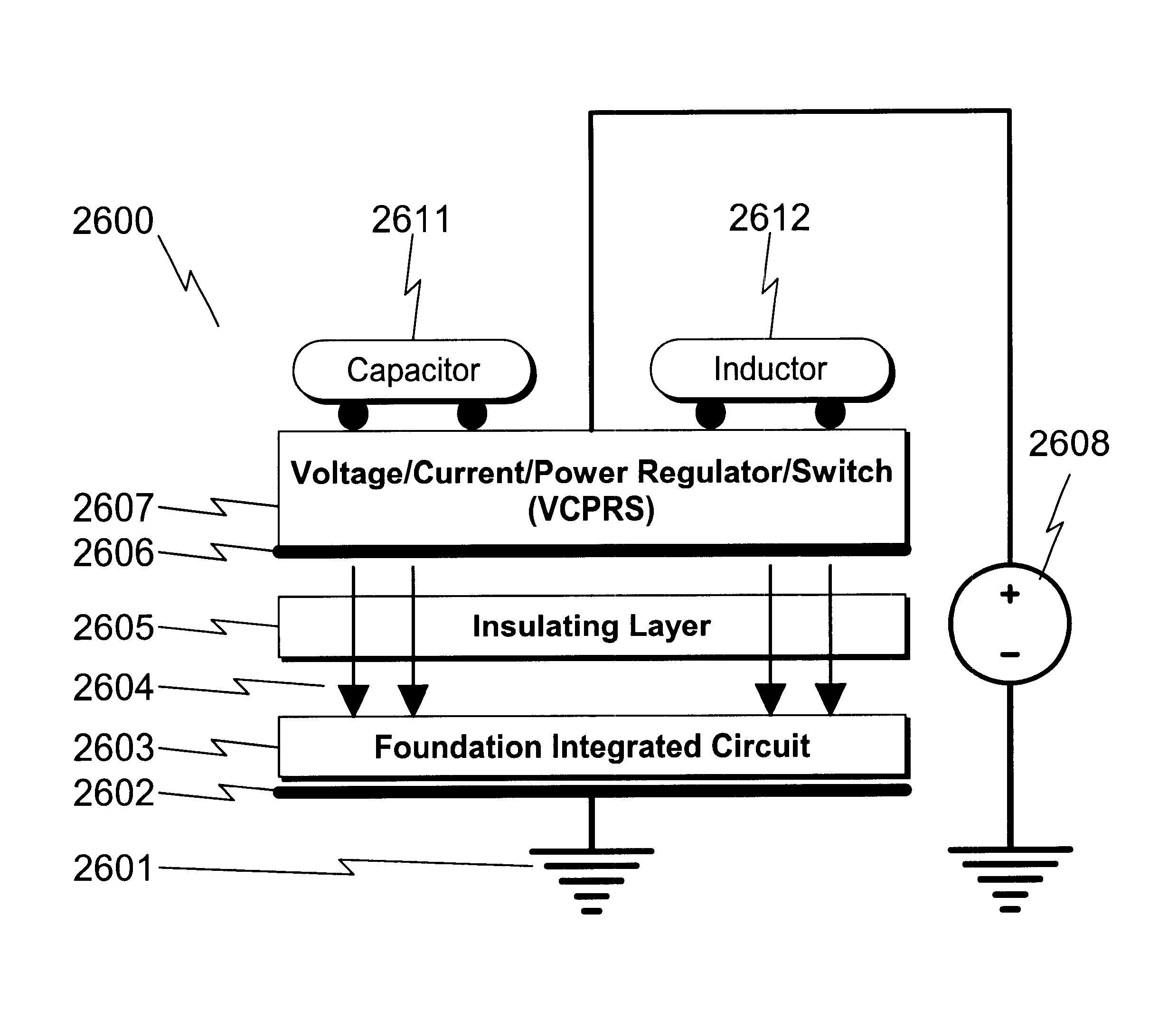
However, there is a limit to this approach, and all of these techniques still demand that the
package leads and bond wires used in the connection process be of a relatively conventional character.
Furthermore, since the fully integrated system is often encapsulated in a metalized
ceramic package, this offers the opportunity to shield the
inductor and the entire switching regulator system and thus affect a significant decrease in EMI for the overall
system configuration.
In these applications it is often burdensome to implement a fully
regulated power supply to support the integrated circuit, and additionally space constraints may make this impractical.
Almost without exception, this circuitry is implemented using discrete components on a
printed circuit board and poses problems from several respects.
Second, the AC
transformer (3702) is often bulky and adds significant weight to the system.
Third, the
voltage regulator (3705) consumes power irrespective of any drain on the power supply terminals (3707).
All of these are minor disadvantages but in the long run result in significant power waste in these systems.
While the industry has sought options to this basic design, there are little if any viable alternatives given the current process technologies.
Since many integrated circuit loads only require a few microamperes of current to operate, the amount of
capacitor plate area required to implement this isolation medium is modest.
However, few practical systems have been put forth to implement such a system.
The major hurdle in implementing these sorts of systems is not one of functionality, but rather integration level and associated cost.
Furthermore, no existing process technology has been able to integrate these functions on a single die at a reasonable cost.
As illustrated in FIG. 31, there do exist a variety of
information appliance system-on-a-
chip configurations, but the level of integration has to date generally precluded the integration of
power switching devices on-chip.
Should one portion of the system fail, there is a potential for a duplicate ABS component to take control and recover braking control.
The cost of this system can obviously beat any discrete implementation, since the cost of
printed circuit board (PCB) is approximately $1 / in.sup.2.
Reducing the component count in this situation definitely saves overall system cost.
While this increase makes sense from a power distribution perspective (note that the power lost in a battery cable is proportional to the
battery voltage drop through the cable squared divided by the cable resistance), this presents some significant problems with future
automotive electronics designs.
This results in increased automobile weight, already a serious issue with electric automobiles.
First, these systems invariably need a power regulator / switch function as the driver for the
serial communication interface.
Unfortunately, the communication aspects of these interfaces makes the integration of these devices expensive and problematic from a reliability standpoint.
This would never be possible / practical using the technology posited by Maxim for their combined RS-232 and UART functionality.
This level of integration has been wanting in the
personal computer market and has severely limited both the low power operation of many products as well as the minimum PCB area required for a given computer system implementation.
While the technology to implement house wiring networks is well known in the art, the capability to integrate this functionality on a single integrated circuit has been lacking in the prior art.
Current
power regulation and power conversion technology cannot support the required
peak current loads without significantly increasing the die size to the point that the chip design becomes uneconomical.

