Multiple-voltage supply power amplifier with dynamic headroom control

a power amplifier and multi-voltage supply technology, applied in the direction of push-pull amplifiers, multi-frequency code systems, push-pull amplifiers, etc., can solve the problems of unpractical "class c" operation, the power consumption of the central office line driving amplifier pair and the power consumption of the central office line is not easy to redu

Inactive Publication Date: 2002-07-09
LEWYN CONSULTING
View PDF4 Cites 54 Cited by
  • Summary
  • Abstract
  • Description
  • Claims
  • Application Information

AI Technical Summary

Problems solved by technology

One disadvantage of this conventional arrangement is its need for power as the number of customers grows.
Because ADSL power amplifiers require low output distortion--typically better than 70 dB for signal to noise-and-distortion ratios--"Class C" operation is not practical.
It is therefore understandable why, despite considerable efforts, many manufacturers have not been possible to reduce power consumption for ADSL central office line driving amplifier pairs significantly below 1.5 W.
On the other hand, if the switching is done abruptly, significant voltage transients may arise on the supply terminals of the output driver device.
This in turn results in increasing noise and distortion components well beyond acceptable limits.
Unfortunately, the capability of supplying nearly a constant headroom over the entire dynamic output range implies providing as much headroom at the lower switch-ove

Method used


Image

  • Multiple-voltage supply power amplifier with dynamic headroom control
  • Multiple-voltage supply power amplifier with dynamic headroom control
  • Multiple-voltage supply power amplifier with dynamic headroom control

Examples


Embodiment Construction

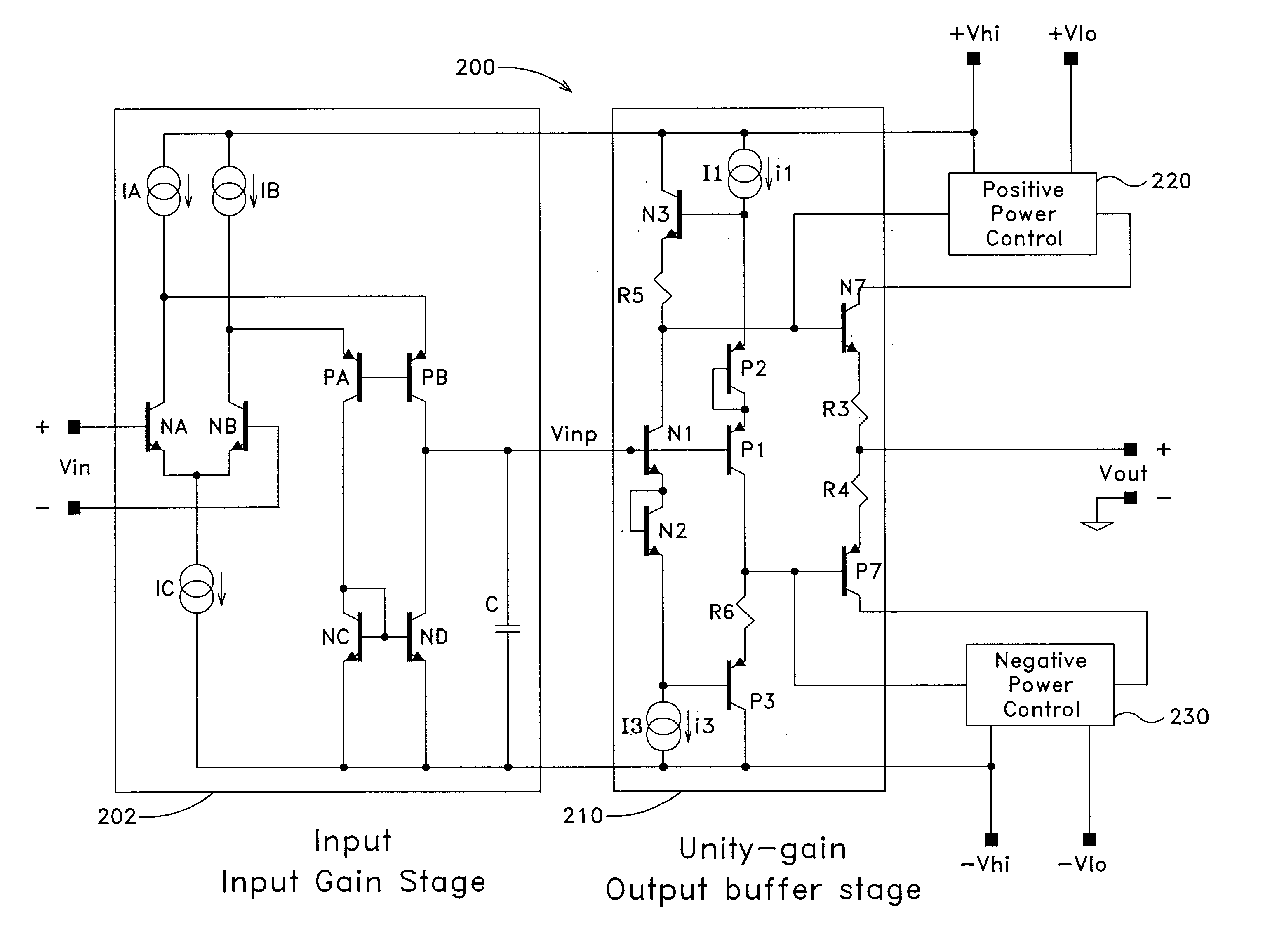
FIG. 3 is a simplified schematic diagram of the output buffer stage with positive and negative power control circuits according to the invention. In FIG. 3, conventional monolithic, bipolar NPN and PNP transistors are indicated with reference designations as Nk and Pk, respectively, (k=1, 2, . . . ). Monolithic diodes are indicated with reference designations as Dk, (k=1, 2, . . . ). Diodes D1 and D2 may be conventional PN junction diodes, but are preferably implemented as Schottky diodes while the remaining diodes are conventional PN junction diodes. Conventional current sources and resistors are similarly indicated as ik and Rk, respectively, (k=1, 2, . . . ).

As is well known, the voltage drop (or rise) over a standard PN junction is roughly 600-800 mV, depending on operating parameters such as temperature (and thus on how much current is passing through the junction). All of the transistors used in the preferred embodiment of the invention are preferably fabricated on the same su...


PUM


Abstract

A monolithic integrated circuit amplifier has a gain stage and a buffer stage. The buffer stage includes an output stage and two separate voltage supplies, the second of which has a greater magnitude than the first. Switching circuitry is included that is connected to the output stage via a regulator bus. When an output demand voltage is less than a switch-over threshold, current to the output stage is provided substantially from the first voltage supply; when the output demand voltage is greater than the switch-over threshold, current to the output stage is provided substantially from the second voltage supply. Collector voltage at the output stage is dynamically controlled to be greater than the emitter voltage by a difference voltage that increases proportionally as output voltage increases above the switch-over threshold. This difference voltage is commonly referred to as "headroom." The dynamic headroom control circuitry preferably includes means for predictably setting and controlling the headroom voltage at switch-over and smoothly increasing the headroom voltage up to maximum output voltage.

Description

1. Field of the InventionThis invention relates to power amplifiers and more particularly to high-power, monolithic, integrated circuit (IC) power amplifiers.2. Background ArtCertain telecommunications standards have been developed in the United States to provide high-speed digital access between customers and a central office. One example is the Asymmetric Digital Subscriber Loop (ADSL) standard, which provides a data rate of approximately 6 Mb in the direction from the central office to the customer. As a result of the high data rate, ADSL has become one of the preferred standards for supplying Internet service over a standard copper wire twisted pair.Although it offers a high data rate, the ADSL standard requires that the line-driving amplifier at the central office be able to supply a signal of approximately 20 dBm (power with respect to a reference level of 1 mW) in power with a peak-to-rms average voltage ratio (PAR) of 5.33:1. In order to accommodate the required power output...

Claims


Application Information

Patent Timeline
IPC IPC(8): H03F1/02H03F3/30H03F3/45H04L27/26H03F3/213
CPCH03F1/0222H03F3/3076H03F3/45094H04L27/2626H03F2203/30078H03F2203/30111H03F2203/45631H04L27/2614
Inventor LEWYN, LANNY L.
Owner LEWYN CONSULTING
Why Eureka
Try Eureka