Abrasive tool with metal binder phase

Inactive Publication Date: 2002-07-16
MITSUBISHI MATERIALS CORP
View PDF16 Cites 74 Cited by
  • Summary
  • Abstract
  • Description
  • Claims
  • Application Information

AI Technical Summary

Benefits of technology

is to provide an abrasive tool with metal binder phase, such as an electrodeposited abr

Problems solved by technology

Then, the problem arises that the polish accuracy and polish efficiency of wafer 6 falls, because the flatness of the polishing surface of the pad 4 falls or clogging occurs by repeating polish of wafer 6.
Then the fault arises that sharpness becomes worse and clogging becomes easy to occur.
Then, the abutment pressure disperses from ultra abrasive grains and becomes slippery, and nap raising could not be cut and fallen down.
Therefore, sharpness becomes worse, and the opening of a foamed layer is crushed, then discharge of ground wastes becomes insufficient.
Consequently, there arises a fault that a pad 4 becomes easy to cause clogging.
Therefore, pad 4 becomes easy to dry and appears a fault that wet grinding becomes spoiled.
If protruded parts are formed at a planate base metal by electroplating etc. the adhesiveness with a base metal becomes worse, then it arises a fault that flaking is easy to occur.
Also, the discrepancy arises, that the protrusions tend to blunt or rises appear at peripheral part by masking.
If there are few ultra abrasive grains less than 11 pieces, rough grinding and finish grinding to pad 4 cannot be performed continuously, and if there are ultra abrasive grains more tha

Method used


Image

  • Abrasive tool with metal binder phase
  • Abrasive tool with metal binder phase
  • Abrasive tool with metal binder phase

Examples


second embodiment

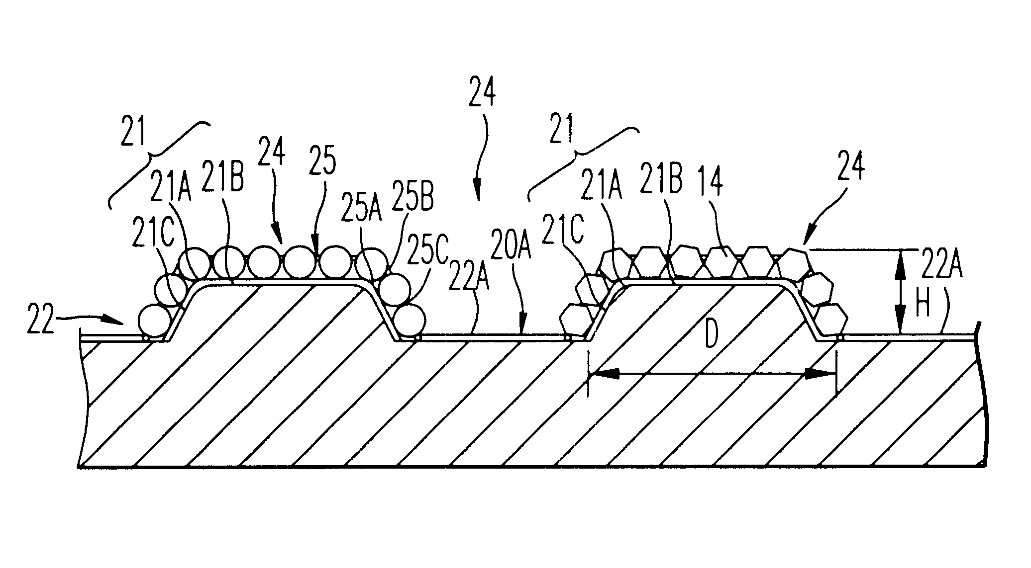
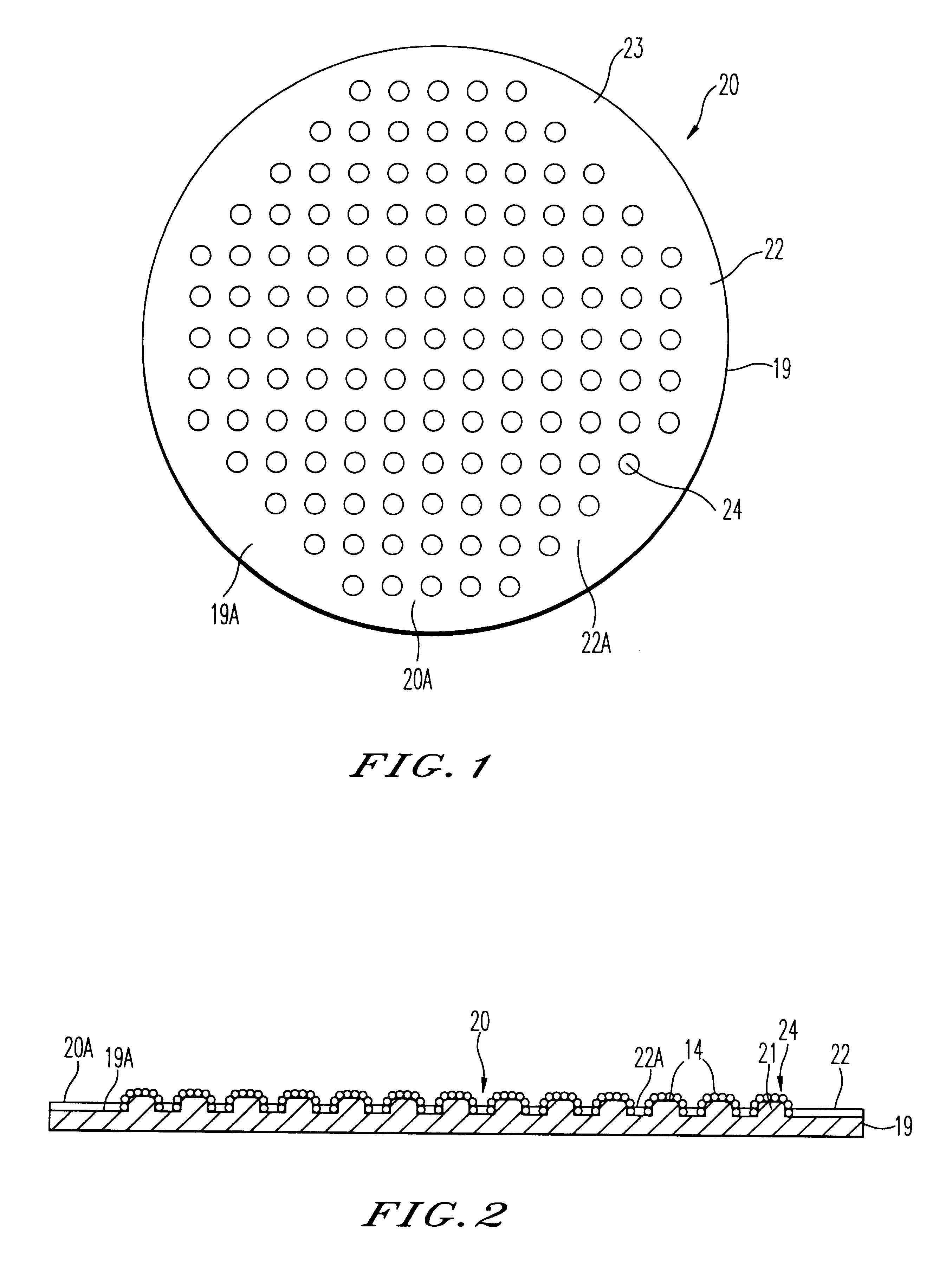
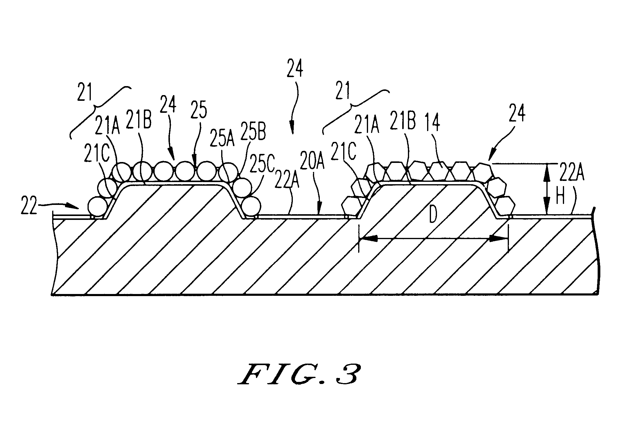
As shown in FIGS. 7 and 8, the electrodeposited abrasive wheel 30 an abrasive grain layer 22 is formed on one-side 19a of base metal 19, and the small abrasive-grain-layer parts 24 are not formed in the central domain 31 of abrasive grain layer 22, but two or more layers of small abrasive-grain-layer parts 24--are arranged at the periphery domain 32 in the shape of concentric circle up to the perimeter edge. Many small abrasive-grain-layer parts 24--with concentric circle shape are mutually separated in the direction of circumference, and diameter. The bottom of abrasive-grain-layer 22a is arranged among the adjoining small abrasive-grain-layer parts 24.

Furthermore, at the abrasive grain layer 22 on single-side 19a, plural ultra-abrasive-grains 14--are adhered only to each smallness abrasive-grain-layer parts 24 with the electrodeposited metal phase 25, respectively.

The electrodeposited abrasive wheel 30 according to the embodiment may be used equipped to the wafer 5, in stead of c...

third embodiment

Subsequently, the present invention is explained.

first embodiment

The electrodeposited abrasive wheel 120 (electrodeposit abrasive tool) according to the embodiment is the same basic composition with the electrodeposited abrasive wheel 20 according to the The surface of the abrasive grain layer 122 corresponds to grinding-surface 20a, and its almost circular central domain is 124, and the ring-like shaped outer domain is the periphery domain 126.

At the one-side 19a of the base metal 19 shown in FIGS. 9 and 10, plural mound parts 21--with almost columnar shape are arranged at the central domain 124 in the shape of lattice, or meshes with predetermined intervals. The convex plane part 127 with ring-like flat plane, whose width is about 3 mm, is formed at the periphery domain 126. The height of the convex plane part 127 is set as the same with mound part 21--.

At the central domain 124, as for the abrasive grain layer 22, plural ultra abrasive grains 14 are adhered by the electrodeposited metal phase 25 only on each mound part 21. The bottom of abras...


PUM


Abstract

In the electrodeposited abrasive wheel 20 of the abrasive tool according to the present invention, plural mound parts 21, which are upheaved at the central domain of base metal 19 in almost columnar shape, are arranged mostly in the shape of lattice. An abrasive grain layer 22 is formed on a base metal 19, and plural ultra abrasive grains 14 are adhered only to each mound parts 21 by electrodeposited metal phase 25, and referred as the small abrasive-grain-layer parts 24, respectively. Ultra abrasive grains are laid out at corner R part 21a and top 21b of the mound parts 21 at the small abrasive-grain-layer parts 24. Ultra abrasive grains at each small abrasive-grain-layer parts are set as 11-500 pieces, and the rate which ultra abrasive grains occupy to the whole area of abrasive grain layer accounted by plane projection is set as 20%-80% of the range. At the time of grinding, only ultra abrasive grains contact to grinding work piece, then high abutment pressure is maintained, and sharpness and the discharge performance of ground wastes are good.

Description

1. Field of the InventionThe present invention relates to an abrasive tool with metal binder phase, containing electrodeposited abrasive tool or metal bonded abrasive tool, used for the conditioner for carrying out conditioning of the polishing pad. Which is used for the polishing of the surface of workpiece, for example, a semiconductor wafer with CMP equipment etc.This specification based on the following Japanese Patent applications (Patent Application number No. 11-247676 (JP), No. 11-247677 (JP), No. 11-269298 (JP), No. 11-338734 (JP), No. 2000-29614 (JP), and the written contents of these concerned Japanese applications are taken in as a part of this specification.2. Background ArtConventionally, there is CMP equipment (Chemical-Mechanical Polishing machine) which chemically and mechanically polishes the surface of the semiconductor wafer (henceforth a wafer) cut down from the silicone ingot, and shown in FIG. 32 as an example.It is required that a mirror polish is carried out...

Claims


Application Information

Patent Timeline
IPC IPC(8): B24D3/04B24D7/06B24D7/00B24D18/00B24D3/06B24B37/04B24B53/12B24B53/017
CPCB24B53/017B24B53/12B24D3/06B24D7/06B24D18/0018
Inventor TAKAHASHI, TSUTOMUSHIMOMAE, NAOKIYAMASHITA, TETSUJIHATA, HANAKO
Owner MITSUBISHI MATERIALS CORP
Why Eureka
Try Eureka