Magneto-optical recording medium

a magnetic field and recording medium technology, applied in the field of magnetic field recording medium, can solve the problems of deteriorating the characteristics of reproduced signals, difficult in practice to lower the required intensity of the modulation magnetic field below 100 oersteds, and difficult to accurately control the recording mark control with optical modulation methods

Inactive Publication Date: 2002-08-20
SEIKO EPSON CORP
View PDF9 Cites 10 Cited by
  • Summary
  • Abstract
  • Description
  • Claims
  • Application Information

AI Technical Summary

Benefits of technology

The objective of the present invention is to provide a magneto-optical recording medium suitable for a magnetic field modulation recording method, with which recording can be properly performed with a smaller modulation magnetic field than in the prior art.

Problems solved by technology

Thus, accurate recording mark control is difficult with optical modulation methods.
Even using these prior arts, it is difficult in practice to lower the required intensity of the modulation magnetic field below 100 Oersteds.
Further, it may happen that the addition of the fourth element or of the additional layer with in-plane magnetization has the secondary effect of deteriorating the characteristics of the reproduced signals.

Method used


Image

  • Magneto-optical recording medium
  • Magneto-optical recording medium
  • Magneto-optical recording medium

Examples


embodiment 1

1. Embodiment 1

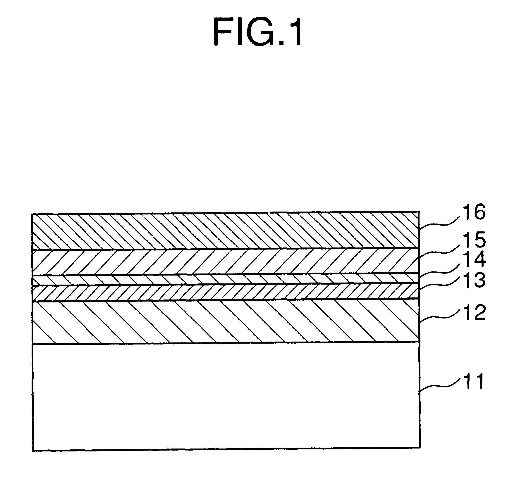
FIG. 1 shows the sectional structure of a first embodiment of the magneto-optical recording medium suitable for recording by a magnetic field modulation method of the present invention. A first dielectric layer 12, a recording layer 13, an auxiliary recording layer 14, a second dielectric layer 15, and a reflective layer 16 are sequentially laminated upon the surface of a transparent substrate 11. The recording layer 13 and the auxiliary recording layer 14 are rare earth-transition metal alloys. The Curie temperature of the auxiliary recording layer 14 is greater than that of the recording layer 13.The thickness of the auxiliary recording layer is less than or equal to 100 angstroms. The exemplary materials for these layers are as follows: the transparent substrate 11 is poly carbonate (PC) substrate; the first dielectric layer 12 and the second dielectric layer 15 are layers of Al--Si--N; the recording layer 13 is a layer of Tb--Fe--Co; the auxiliary recording layer ...

embodiment 2

2. Embodiment 2

FIG. 11 shows the sectional structure of a magneto-optical recording medium of this embodiment. A first dielectric layer 12, an auxiliary recording layer 14, a recording layer 13, a second dielectric layer 15, and a reflective layer 16 are sequentially laminated upon a transparent substrate 11. Thus, the only difference as compared with the medium which was shown in FIG. 1 is that the order of superimposition of the recording layer 13 and the auxiliary recording layer 14 is opposite.

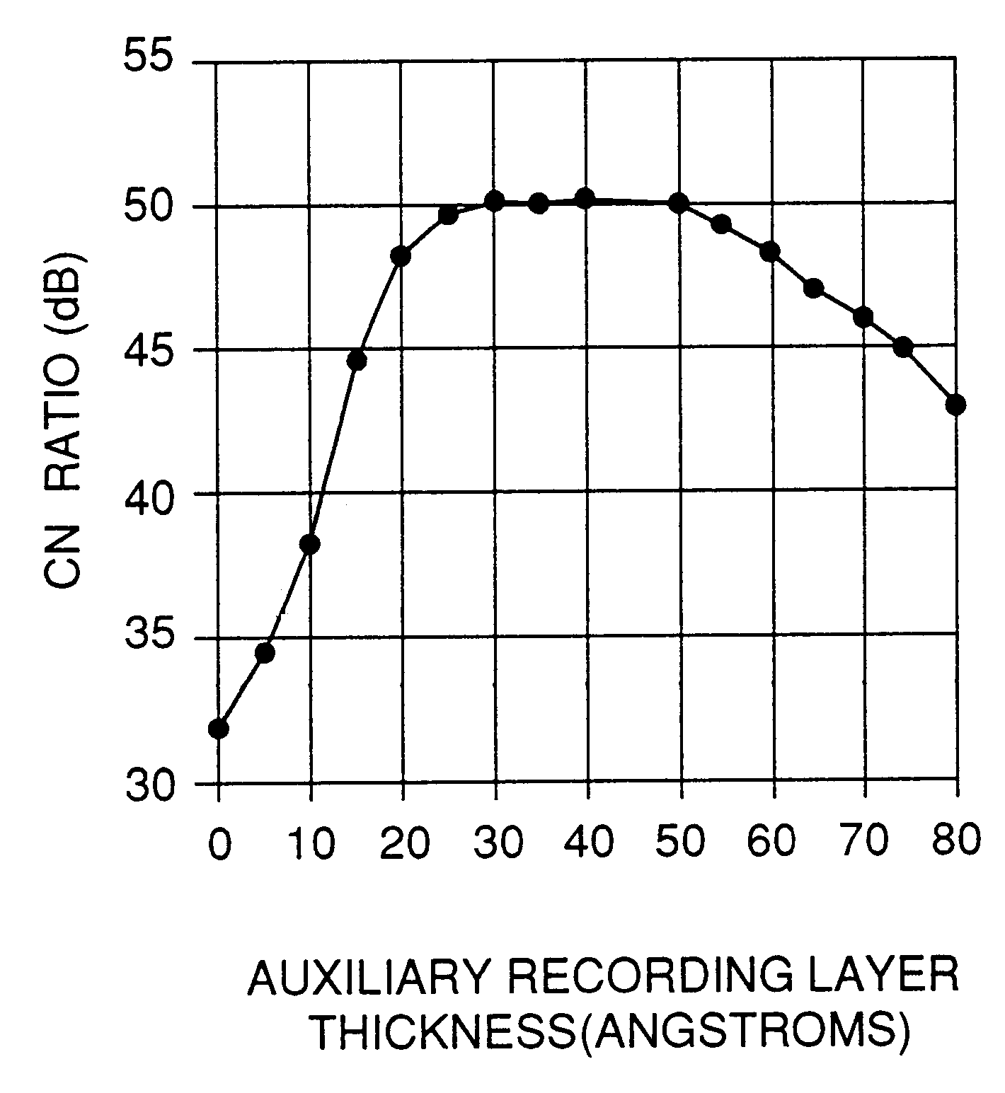
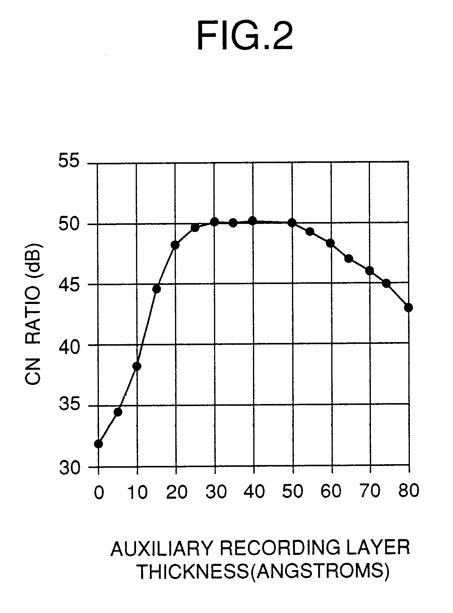
(1) Experiment 6: Relationship between the film thickness of the auxiliary recording layer 14 and the magnetic field sensitivity.

Here, a rare earth-transition metal alloy having the composition Tb0.15(Fe0.91Co 0.09)0.85 was used as the recording layer 13. This layer 13 was formed by DC magnetron sputtering, using a target manufactured by alloy casting, under the following conditions: argon gas pressure 1.8 mTorr; and supplied power 300 W. Its Curie temperature was 190 C.

A rare earth-transi...

embodiment 3

3. Embodiment 3

FIG. 13 shows the sectional structure of a magneto-optical recording medium of this embodiment. In this embodiment, the auxiliary recording layer is interposed in the space between two recording layers 13-1 and 13-2. In other words, a first dielectric layer 12, a first recording layer 13-1, an auxiliary recording layer 14, a second recording layer 13-2, a second dielectric layer 15, and a reflective layer 16 are sequentially laminated upon a transparent substrate 11.

(1) Experiment 7: Relationship between the film thickness of the auxiliary recording layer 14 and the magnetic field sensitivity.

Here, a rare earth-transition metal alloy having the composition Tb0.16(Fe0.8Co 0.20)0.84 was used for the recording layers 13-1 and 13-2. These layers 13-1 and 13-2 were formed by DC magnetron sputtering, using a target manufactured by alloy casting, under the following conditions: argon gas pressure 1.8 mTorr; and supplied power 300 W. Their Curie temperature was 240 degrees ce...


PUM

PropertyMeasurementUnit
thicknessaaaaaaaaaa
Curie temperatureaaaaaaaaaa

Abstract

When recording using magnetic field modulation recording, the magneto-optical recording medium which is disclosed is capable of satisfactory recording with a low magnetic field. This recording medium is a layered superposition of a recording layer 13 and an auxiliary recording layer 14 having a film thickness of less than or equal to 100 angstroms. The recording layer 13 is a film having an easy perpendicular axis of magnetization whose value of magnetization at room temperature is at least 150 emu/cc, and for example a heavy rare earth-transition metal alloy, a magnetic multilayer film which employs a precious metal, an oxide like a garnet or Spinel ferrite, or some other magnetic alloy may be used. The auxiliary recording layer 14 is typically a heavy rare earth-transition metal alloy, and has a Curie temperature higher (desirably at least 30K higher) than that of the recording layer 13. It is desirable to further provide a stabilizing layer superimposed upon the recording layer 13 which has a lower Curie temperature and also a higher coercive field at room temperature than the recording layer recording layer 13. If HREx(Fe1-yCoy)1-x is used for the recording layer recording layer 13 (here HRE is a heavy rare earth metal), it is desirable that 0.08<=x<=0.20 and also 0.0<=y<=0.3.

Description

The present invention relates to a magneto-optical recording medium, and in particular relates to a magneto-optical recording medium adapted to the use of a magnetic field modulation recording method.Methods for recording upon magneto-optical recording media can be broadly divided into optical modulation methods and magnetic field modulation recording methods. An optical modulation method is a method in which recording marks (magnetic domains) are formed by blinking a recording laser while applying a constant magnetic field to the medium. And a magnetic field modulation recording method is a method in which recording marks are formed upon the medium by varying a magnetic field while illuminating the medium with a recording laser at a constant power or with pulses of constant period and constant width. A magnetic field modulation recording method can be easily overwritten, and is suitable for mark edge recording. Here, mark edge recording means a method of recording in which channel ...

Claims


Application Information

Patent Timeline
Patent Type & Authority Patents(United States)
IPC IPC(8): G11B11/00G11B11/105
CPCG11B11/10584G11B11/10586G11B11/10508Y10T428/265Y10S428/90Y10T428/26G11B11/10
Inventor ISHIDA, MASAYAKAWASE, TAKEO
Owner SEIKO EPSON CORP
Why Eureka
Try Eureka