Large surface area x-ray tube window and window cooling plenum

a technology of x-ray tube and cooling plenum, which is applied in the field of large surface area x-ray tube window and window cooling plenum, can solve the problems of reducing the service life of x-ray tube components, generating significant amount of heat, and destroying x-ray tubes, and achieving the effect of effectively and efficiently removing excessive heat from x-ray tube components

Inactive Publication Date: 2002-08-20
VAREX IMAGING CORP
View PDF13 Cites 43 Cited by
  • Summary
  • Abstract
  • Description
  • Claims
  • Application Information

AI Technical Summary

Benefits of technology

The present invention has been developed in response to the current state of the art, and in particular, in response to these and other problems and needs that have not been fully or adequately solved by currently available x-ray tube cooling systems. Thus, it is an overall object of embodiments of the present invention to provide a cooling system that effectively and efficiently removes excessive heat from x-ray tube components.

Problems solved by technology

These secondary electrons retain a significant amount of kinetic energy after rebounding, and when they impact these other non-target surfaces, a significant amount of heat is generated.
As discussed in further detail below, the heat thus generated can ultimately damage the x-ray tube, and shorten its operational life.
In particular, the temperatures generated by secondary electrons, in conjunction with the high temperatures generated by the primary electrons at the focal spot of the target surface, often reach levels high enough to damage portions of the x-ray tube structure.
In some instances, the resulting temperatures can even melt portions of the x-ray tube, such as lead shielding disposed on the can.
Such conditions can shorten the operating life of the tube, affect its operating efficiency, and / or render it inoperable.
Further, because the trajectories of secondary electrons cause them to impact some interior surface locations with relatively greater frequency than other areas, the resulting heat distribution can be uneven.
Ultimately, this can cause a mechanical failure in the part, especially over numerous operating cycles.
While the aforementioned problems are cause for concern in all x-ray tubes, these problems become particularly acute in the new generation of high-power x-ray tubes (generally, those x-ray tubes with operating powers exceeding 20 kilowatts (kw)) which have relatively higher operating temperatures than the typical devices.
Note that the problems herein described are also cause for concern where long exposures, or exposure chains, are being performed, regardless of the power of the x-ray tube performing the exposures.
However, previously available x-ray tube cooling systems have not been entirely satisfactory in providing effective and efficient cooling, and have been especially ineffectual in those particular regions of the tube that are subjected to high temperatures, such as from rebounding electrons.
Moreover, the inadequacies of known x-ray tube cooling systems are further exacerbated by the increased heat levels that are characteristic in high-powered x-ray tubes.
While these types of processes are adequate to cool some portions of the x-ray tube, they may not adequately cool areas of localized heat--such as those that are particularly susceptible to heating from secondary electrons, including the window area of the tube, the window itself, and portions of the can structure that are proximate to the window area.
The joint where the x-ray tube window is attached to the can is also particularly vulnerable to thermally induced damage, due largely to the relatively close proximity of this joint to the cathode and anode, and may not be adequately cooled by conventional cooling systems and processes.
Not only does its close proximity to the cathode and anode render the window especially susceptible to thermally induced damage, but certain characteristics of the window itself also make the window vulnerable to such damage.
For example, because the window is relatively thin and is typically constructed of a material having a low atomic number, such as beryllium, it is relatively more susceptible to heat damage.
As suggested above, the window area of the x-ray tube, and the window itself, are particularly susceptible to heat induced structural damage, due at least in part to their proximity to the target anode, and the cathode.
Heat levels such as this can induce potentially destructive mechanical stresses in the window and the joint between the window and the can.
A related, and undesirable, consequence is that the bubbles produced by boiling of the coolant may obscure the window of the x-ray tube and thereby compromise the quality of the images produced by the x-ray device.
Further, boiling of the coolant can result in the chemical breakdown of the coolant, thereby rendering it ineffective, and necessitating its removal and replacement.

Method used


Image

  • Large surface area x-ray tube window and window cooling plenum
  • Large surface area x-ray tube window and window cooling plenum
  • Large surface area x-ray tube window and window cooling plenum

Examples


Embodiment Construction

Reference will now be made to figures wherein like structures will be provided with like reference designations. It is to be understood that the drawings are diagrammatic and schematic representations of various embodiments of the invention, and are not to be construed as limiting the present invention, nor are the drawings necessarily drawn to scale.

In general, the present invention relates to cooling systems for use in any type of x-ray tube environment requiring improved cooling. FIGS. 1 through 7 indicate various embodiments of a cooling system conforming to the teachings of the invention.

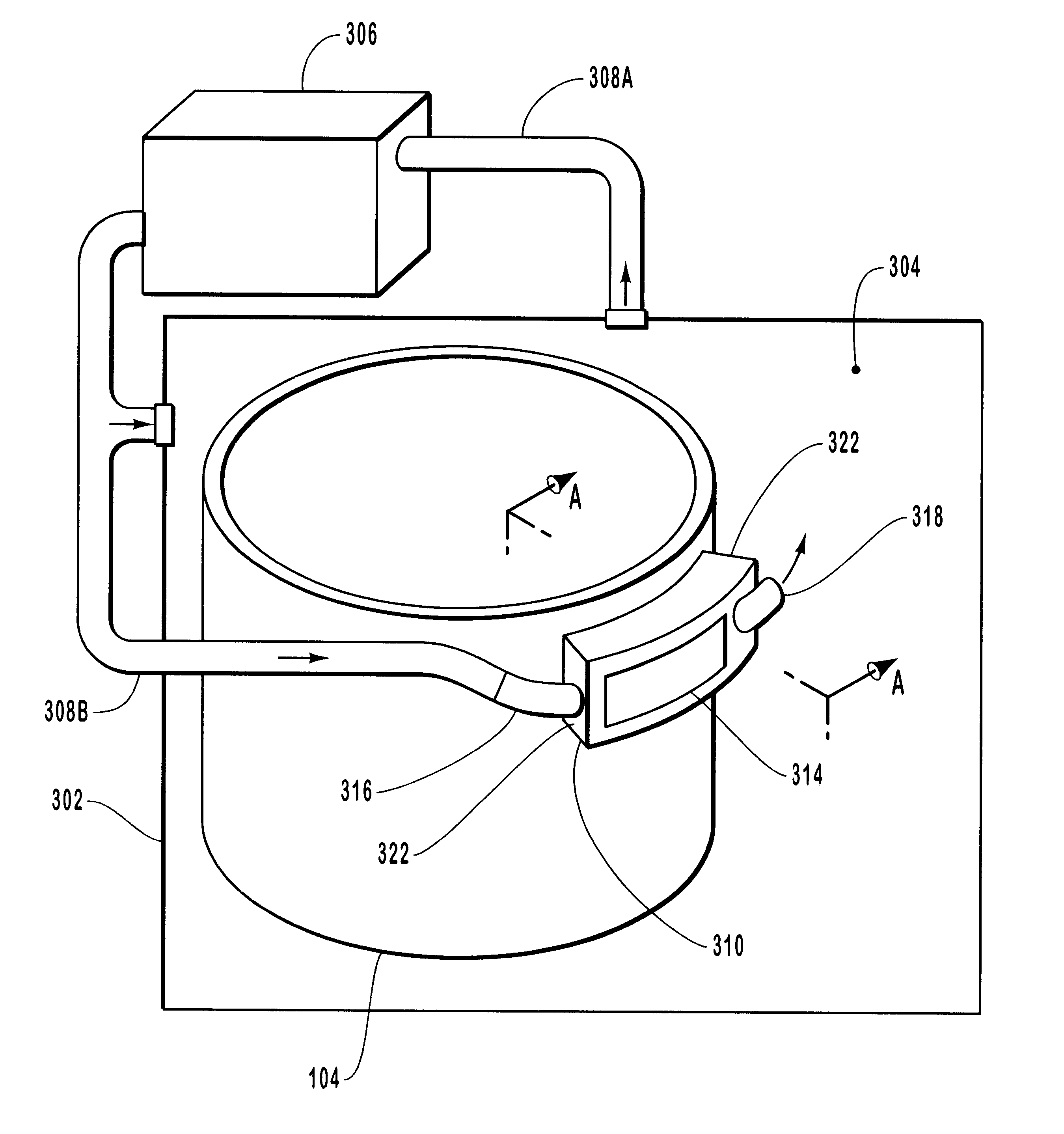
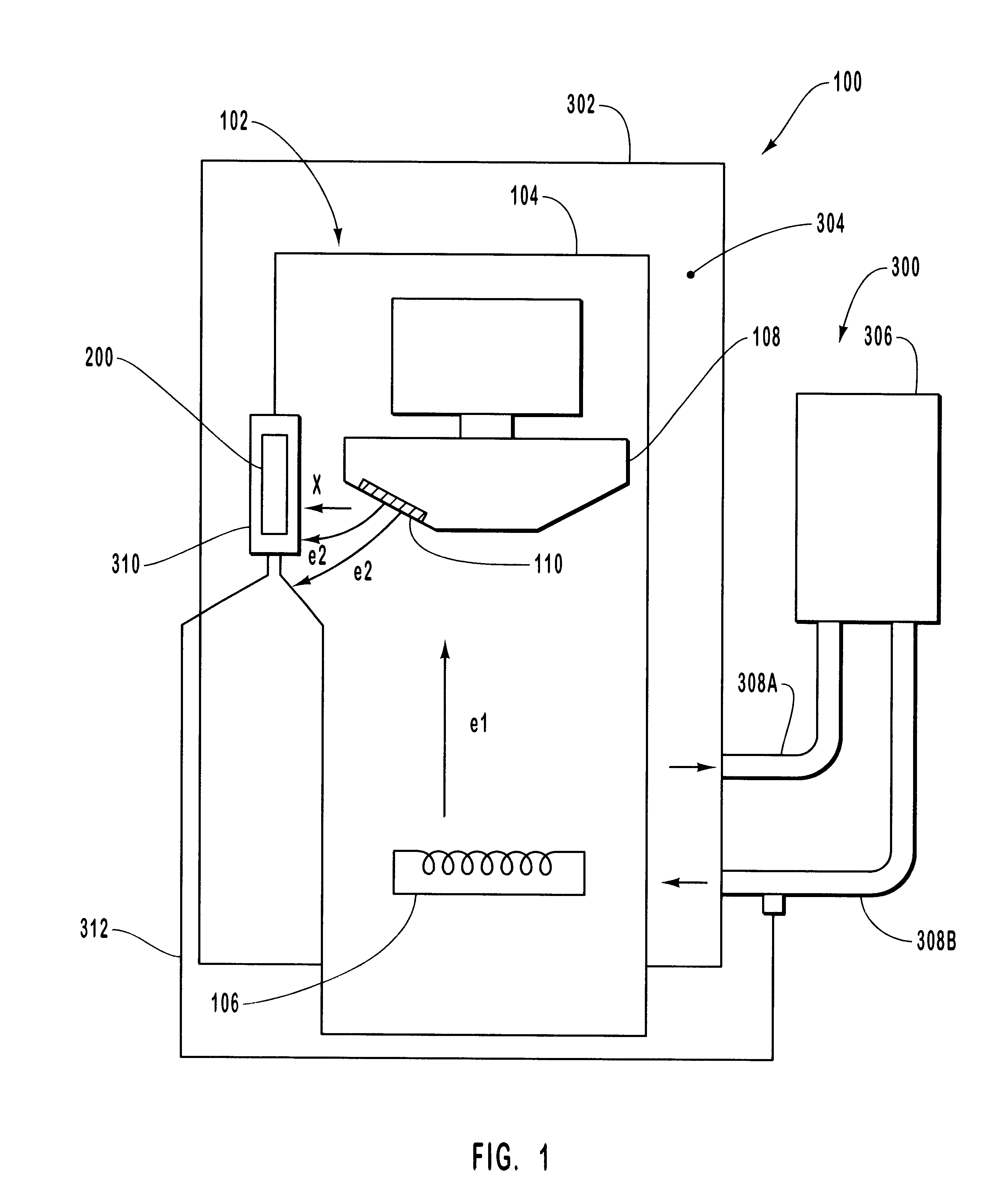
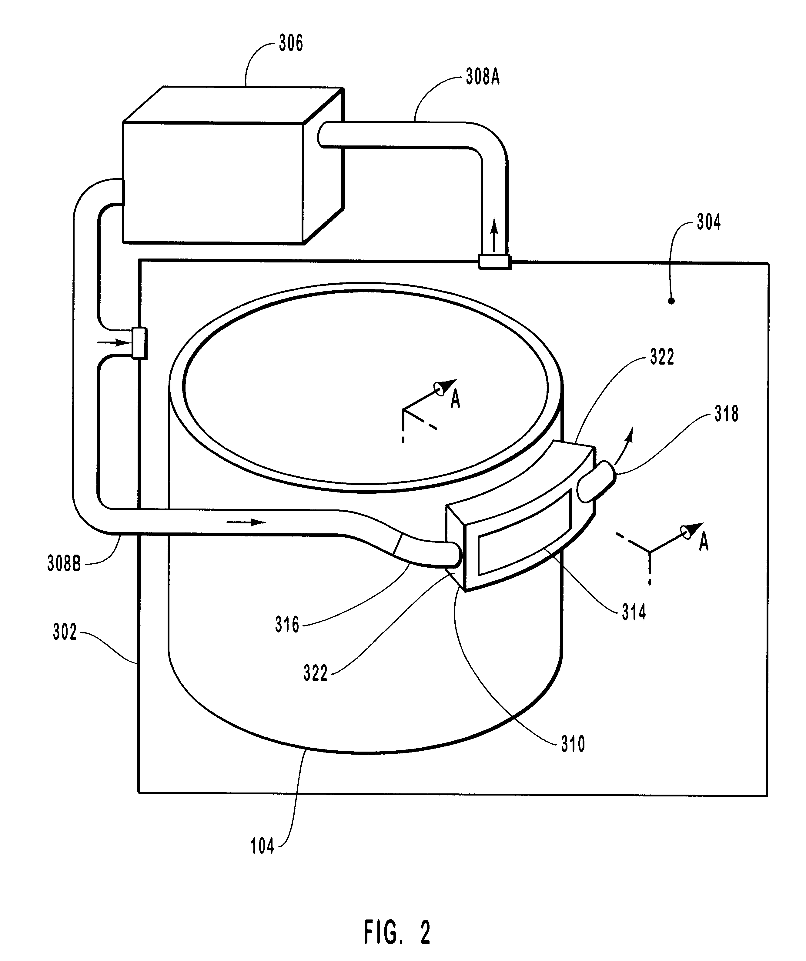
Reference is first made to FIG. 1, which depicts an x-ray device indicated generally at 100. X-ray device 100 includes an x-ray tube 102 having a vacuum enclosure 104, inside of which are disposed an electron source 106 and a target anode 108. In operation, power is applied to electron source 106, which causes a beam of electrons e1 to be emitted by thermionic emission. A potential difference i...


PUM


Abstract

A window and cooling plenum for use with x-ray devices. The x-ray device includes an x-ray tube at least partially immersed in coolant contained within a reservoir. The coolant is continuously circulated through the reservoir by an external cooling unit. The window is brazed into a vacuum enclosure of the x-ray tube and includes a plurality of extended surfaces that are integral with the window. A compensating window is also provided and is disposed substantially proximate to the extended surfaces of the window so that a fluid passageway is defined. The compensating window and window are substantially enclosed within a cooling plenum having fluid inlet and outlet connections in fluid communication with the fluid passageway and the reservoir. A flow of coolant generated by the external cooling unit enters the fluid passageway so that the coolant is able to absorb heat dissipated by the window. Upon exiting the fluid passageway, the coolant returns to the reservoir to repeat the cycle. In addition to facilitating definition of the fluid passageway, the compensating window includes extended surfaces and slots which serve to attenuate differences in the intensity of x-rays emitted through the extended surfaces and slots of the window. By ensuring that the x-rays ultimately emitted from the x-ray device are of substantially uniform intensity, the compensating window serves to maintain the quality of diagnostic images produced by the x-ray device.

Description

The present invention relates generally to x-ray tubes. More particularly, embodiments of the present invention relate to an x-ray tube cooling system that increases the rate of heat transfer from the x-ray tube to a cooling system medium so as to significantly reduce heat-induced stress and strain in the x-ray tube structures and thereby extend the operating life of the deviceTHE PRIOR STATE OF THE ARTX-ray producing devices are extremely valuable tools that are used in a wide variety of applications, both industrial and medical. For example, such equipment is commonly used in areas such as diagnostic and therapeutic radiology; semiconductor manufacture and fabrication; and materials analysis and testing. While used in a number of different applications, the basic operation of x-ray tubes is similar. In general, x-rays, or x-ray radiation, are produced when electrons are produced, accelerated, and then impinged upon a material of a particular composition.Typically, this process is ...

Claims


Application Information

Patent Timeline
Patent Type & Authority Patents(United States)
IPC IPC(8): G21K5/04H01J35/18H01J35/00H05G1/00H05G1/04
CPCG21K5/04H01J35/18H05G1/04H05G1/025H01J2235/122
Inventor KOLLER, THOMAS J.
Owner VAREX IMAGING CORP
Why Eureka
Try Eureka