Extreme ultraviolet soft x-ray projection lithographic method and mask devices

a technology of ultraviolet soft x-ray and projection lithography, which is applied in the field of projection lithographic methods, can solve the problems of adoption affecting the commercial and affecting the use of extreme ultraviolet soft x-rays

Inactive Publication Date: 2002-10-15
CORNING INC
View PDF65 Cites 63 Cited by
  • Summary
  • Abstract
  • Description
  • Claims
  • Application Information

AI Technical Summary

Problems solved by technology

The use of extreme ultraviolet soft x-ray radiation provides benefits in terms of achieving smaller feature dimensions but due to the nature of the radiation, it presents difficulties in terms of manipulating and directing such wavelengths of radiation and has delayed the commercial manufacturing use of such radiation.
Current optical lithography systems used in the manufacturing of integrated circuits have progressed towards shorter optical wavelengths of light, such as from 248 nm to 193 nm to 157 nm, but the commercial use and adoption of extreme ultraviolet soft x-rays has been hindered.
Part of this slow progression to very short wavelengths of radiation such as in the 15 nm range, has been due to the lack of economically manufacturable reflective mask wafers that can withstand the exposure to such radiation while maintaining a stable and high quality circuit pattern image.
As noted from U.S. Pat. No. 5,698,113, current extreme ultraviolet soft x-ray lithographic systems are extremely expensive.

Method used


Image

  • Extreme ultraviolet soft x-ray projection lithographic method and mask devices
  • Extreme ultraviolet soft x-ray projection lithographic method and mask devices
  • Extreme ultraviolet soft x-ray projection lithographic method and mask devices

Examples


Embodiment Construction

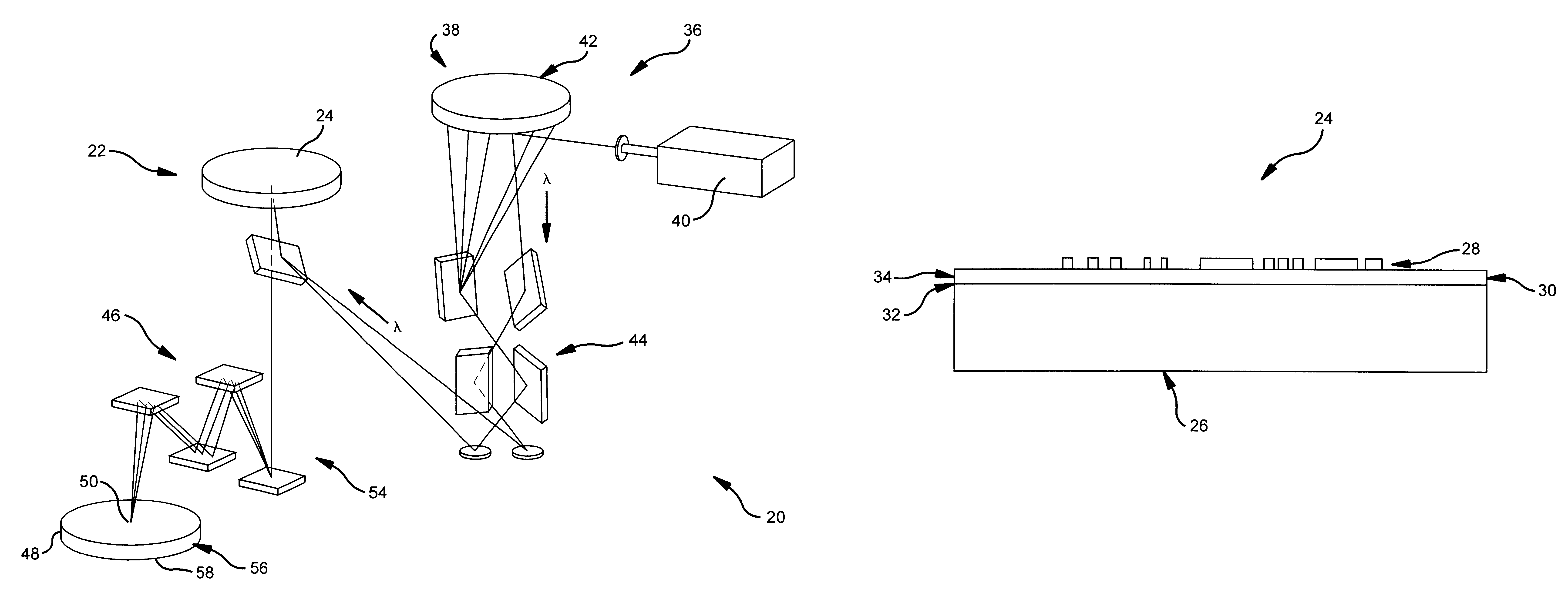
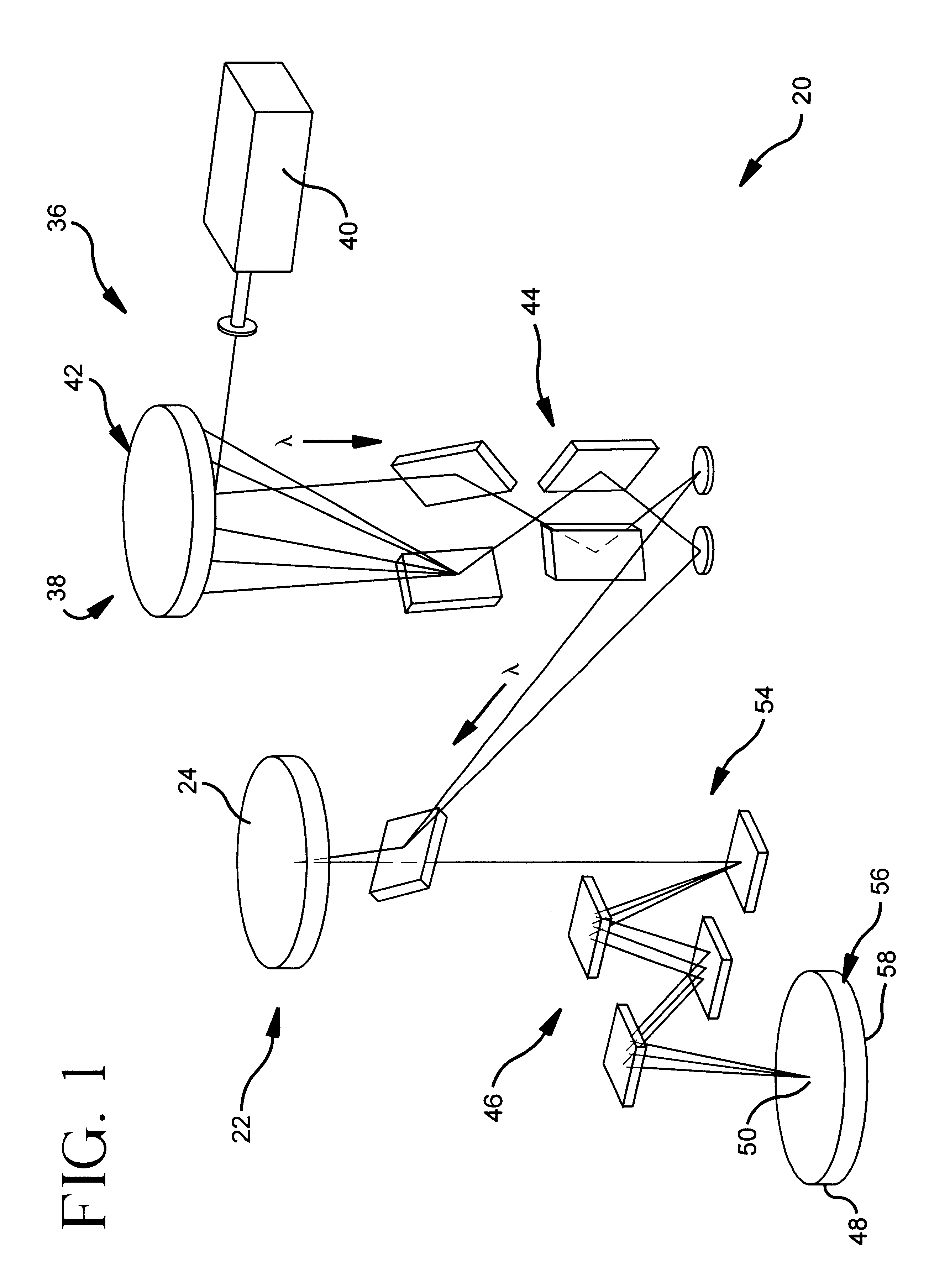
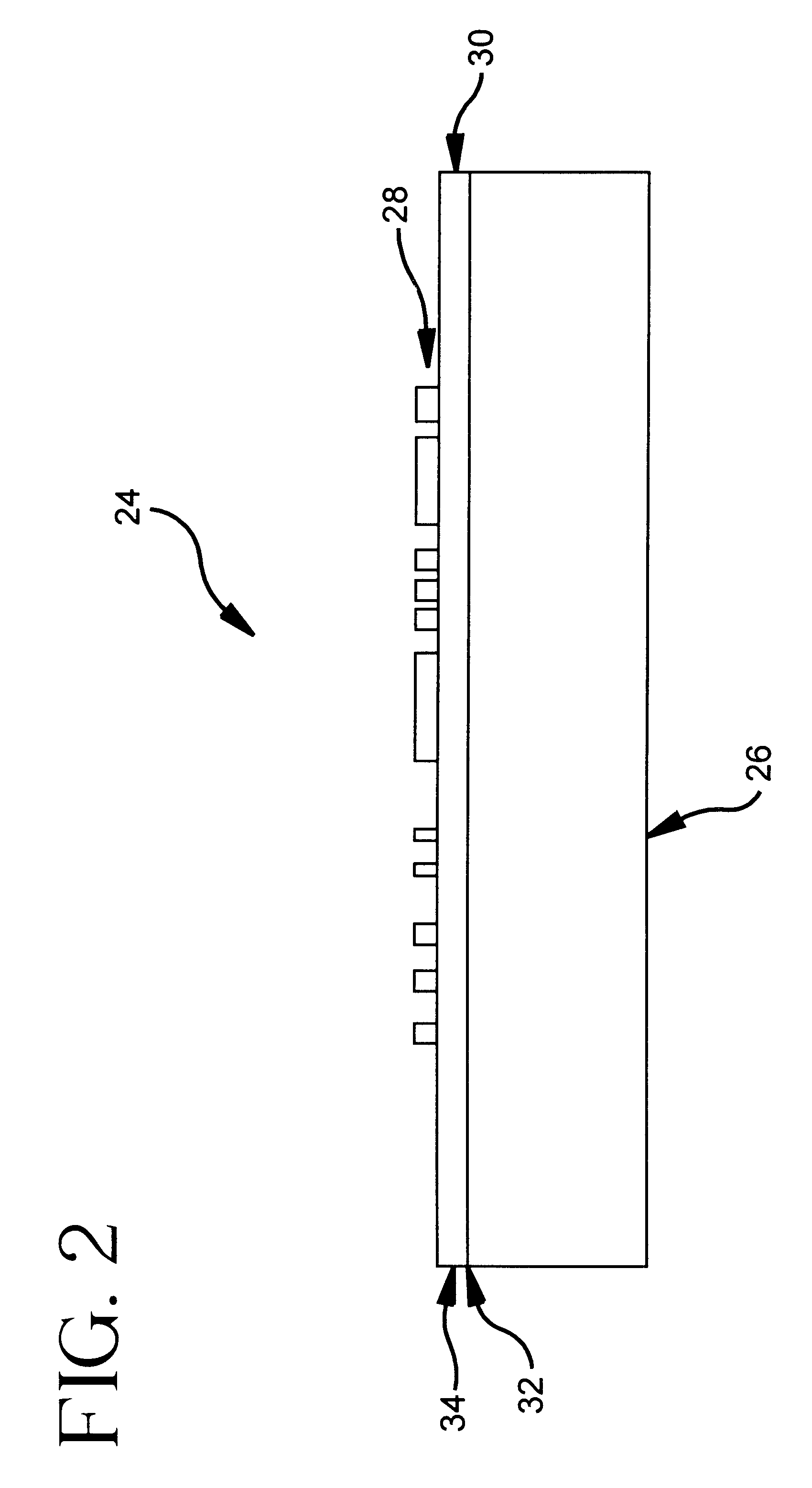
FIGS. 5A-5B are AFM photomicrographs of a Ti doped high purity SiO.sub.2 glass wafer surface. FIGS. 5A-5B were taken at two separate locations on the same finished wafer sample top surface. The mask wafer sample was obtained by finishing a Ti doped high purity SiO.sub.2 glass preform that was free of inclusions. The preform had a square shape with approximately 7.6 cm sides and a thickness of approximately 0,64 cm. The square preform was obtained by cutting the preform from an inclusion free area of a Ti doped high purity SiO.sub.2 glass boule that had a cylindrical shape of approximately 152 cm diameter and a 14 cm thickness (height). The boule was produced from octamethylcyclotetrasiloxane and titanium isopropoxide feedstocks in accordance with FIG. 6 of the invention with the Ti doped high purity SiO.sub.2 glass having a TiO.sub.2 wt. % of about7.5 wt. %. The square preform were finished into a planar mask wafer using a double sided lapping / polishing machine. The square preform w...


PUM

PropertyMeasurementUnit
operating temperatureaaaaaaaaaa
reflectivityaaaaaaaaaa
Ra roughness≤0aaaaaaaaaa

Abstract

The present invention relates to reflective masks and their use for reflecting extreme ultraviolet soft x-ray photons to enable the use of extreme ultraviolet soft x-ray radiation projection lithographic methods and systems for producing integrated circuits and forming patterns with extremely small feature dimensions. The projection lithographic method includes providing an illumination sub-system for producing and directing an extreme ultraviolet soft x-ray radiation lambd from an extreme ultraviolet soft x-ray source; providing a mask sub-system illuminated by the extreme ultraviolet soft x-ray radiation lambd produced by the illumination sub-system and providing the mask sub-system includes providing a patterned reflective mask for forming a projected mask pattern when illuminated by radiation lambd. Providing the patterned reflective mask includes providing a Ti doped high purity SiO2 glass wafer with a patterned absorbing overlay overlaying the reflective multilayer coated Ti doped high purity SiO2 glass defect free wafer surface that has an Ra roughness<=0.15 nm. The method includes providing a projection sub-system and a print media subject wafer which has a radiation sensitive wafer surface wherein the projection sub-system projects the projected mask pattern from the patterned reflective mask onto the radiation sensitive wafer surface.

Description

FIELD OF THE INVENTIONThe present invention relates generally to projection lithographic methods and systems for producing integrated circuits and forming patterns with extremely small feature dimensions. The present invention relates particularly to extreme ultraviolet soft x-ray based lithography and reflective masks which reflect extreme ultraviolet soft x-ray radiation and form pattern images that are utilized to form circuit patterns. The present invention relates to reflective masks and their use for reflecting extreme ultraviolet soft x-ray photons to enable the use of extreme ultraviolet soft x-ray radiation for lithography that surpasses current optical lithography circuit feature dimension performance.TECHNICAL BACKGROUNDThe use of extreme ultraviolet soft x-ray radiation provides benefits in terms of achieving smaller feature dimensions but due to the nature of the radiation, it presents difficulties in terms of manipulating and directing such wavelengths of radiation and...

Claims


Application Information

Patent Timeline
Patent Type & Authority Patents(United States)
IPC IPC(8): G03F7/20G03F1/14G03F1/00G03F1/24G03F1/60G21K1/06H01L21/027
CPCB82Y10/00B82Y40/00G03F1/14G03F1/24G03F1/60G03F7/702G03F7/70233G03F7/70283G03F7/70891G03F7/70958G21K1/062G02B17/06Y10S438/947Y10S438/974
Inventor DAVIS, JR., CLAUDE L.HRDINA, KENNETH E.SABIA, ROBERTSTEVENS, HARRIE J.
Owner CORNING INC
Why Eureka
Try Eureka