
Glazing with variable optical and/or energetic properties

a technology of energetic properties and variable optical properties, applied in the field of gla, can solve the problems of progressive irreversible degradation, shortening the lifetime of the glazing, and affecting the appearance of the building, so as to prolong the lifetime of the intelligent glazing, modulate the optical appearance, and improve the thermal performan

Inactive Publication Date: 2002-10-15
SAINT-GOBAIN GLASS FRANCE
View PDF7 Cites 91 Cited by
  • Summary
  • Abstract
  • Description
  • Claims
  • Application Information

AI Technical Summary

Benefits of technology

The first object of the present invention is to provide new glazings with variable optical and / or energetic properties that overcome the above disadvantages and are capable of being controlled electrically or photochromically, which exhibit a greater thermal durability and / or whose optical appearance can be modulated to a greater extent.
Another object of the present invention is to provide a glazing in which excessive heating of the active system is prevented.
Another object of the present invention is to provide an "intelligent" glazing that can be fitted externally to buildings or vehicles and can be exposed to long periods of sunshine.
Another object of the present invention is to provide a glazing in which the photochromic properties have an extended lifetime, and are not degraded with excessive heating or exposure to radiation.
Another object of the present invention is to provide an "intelligent" glazing having exceptional durability to visible, ultraviolet, and infrared radiation.

Problems solved by technology

However, all of the above glazings exhibit intrinsic limits with respect to their thermal behavior and to their optical appearance.
Such temperatures can cause a shortening of the lifetime of the glazings by progressive irreversible degradation of one or other of their electrochemical components.
The same type of problem can also arise in the case of glazings with variable light diffusion, like liquid-crystal glazings.
Subsequently, if a dichroic dye has been added to the composite in order to make it possible to modulate both the light diffusion and transmission of the glazing, this type of dye exhibits some degree of instability in the ultraviolet region, an instability that increases with temperature.
Photochromic glazings also have a disadvantage linked with their heating.
In strong sunshine the heating becomes excessive and tends to make the glazings revert to their faded stable state, and the "available" contrast decreases.
Furthermore, the optical appearance of the above glazings may not be fully satisfactory, depending on the intended applications.

Method used


Image

  • Glazing with variable optical and/or energetic properties
  • Glazing with variable optical and/or energetic properties
  • Glazing with variable optical and/or energetic properties

Examples


example 1

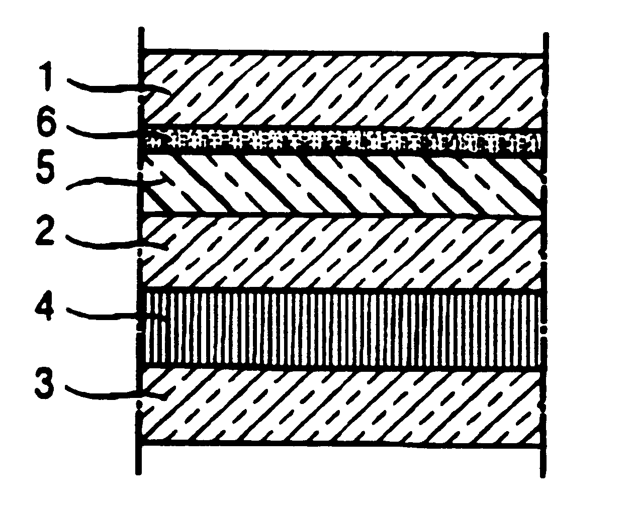
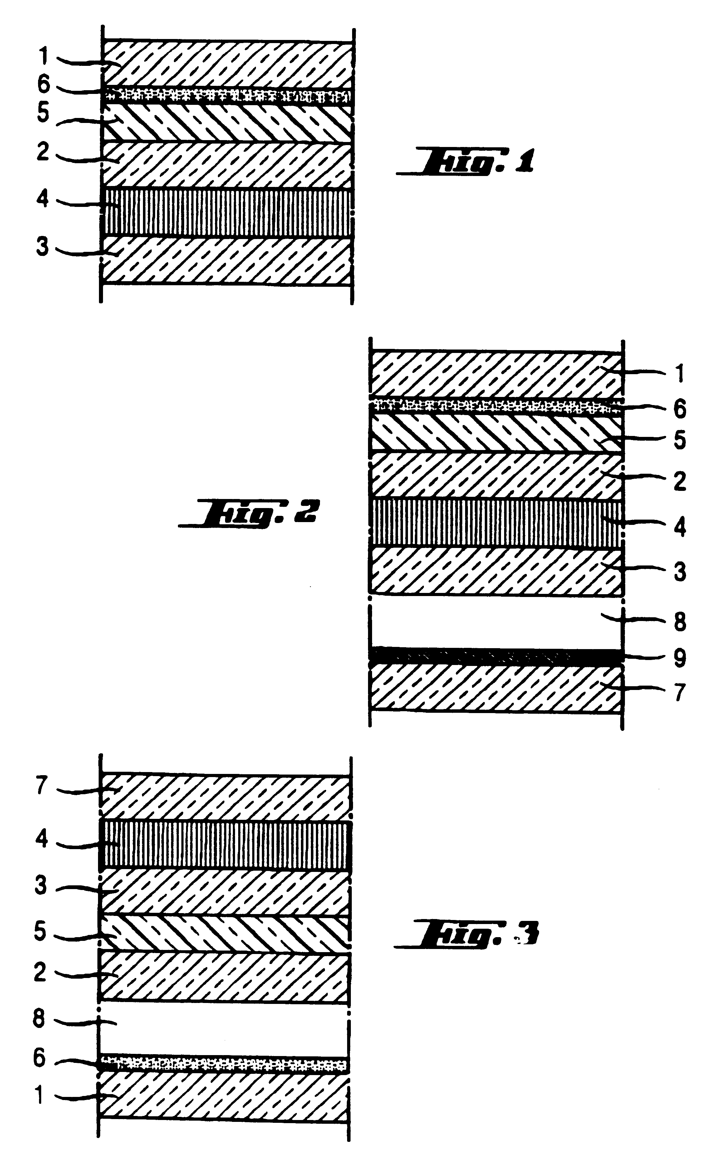
FIG. 1 shows an electrochromic glazing of laminated structure containing three glasses in a configuration adapted, for example, to use as a car roof: two clear glasses 2, 3 are shown, between which is placed an electrochromic system 4 consisting of the stack of the following functional layers (stack in accordance with the teaching of EP-0 628 849, the contents of which are hereby incorporated by reference):

a 300 nm first electroconducive layer of SnO.sub.2 :F,

a 55 nm first layer of anodic electrochromic material made of hydrated iridium oxide (it could preferably be replaced with a layer of hydrated nickel oxide).

a 70 nm layer of hydrated tantalum oxide (Ta.sub.2 O.sub.5.H.sub.x), its function being protection.

a layer of electrolyte as solid solution of polyethylene oxide with phosphoric acid (PEO--H.sub.3 PO.sub.4), of 100 micrometers,

a 350 nm second layer of cathodic electrochromic material based on tungsten oxide,

a 300 nm second layer of SnO.sub.2 :F.

The glass 2+electrochromic sy...

example 2

Example 2 corresponds to the electrochromic glazing configuration shown in FIG. 2: the glasses 1, 2, 3 of FIG. 1 are seen again, as is the name PVB sheet 5, the same reflecting coating 6 and the same electrochromic system 4. The three-glass unit has been fitted as double glazing with the aid of a fourth clear glass 7 through the intermediacy of a layer of argon 8, 12 mm in thickness, with the aid of means of assembly which are known in the field of double glazing and are not shown.

On the face of the glass 7 facing the argon layer 8 is placed a coating 9 with low-emissivity properties, of the type of those applied to the glazings marketed under the name of Planitherm by Saint-Gobain Vitrage, that is the following stack:

a 40 nm layer of tin oxide,

a 9 nm layer of silver,

a 40 nm layer of tin oxide, together with, as in the case of the stack 6 described above, the presence of two thin layers of 0.5 to 1.5 nm of Ni--Cr, intended to protect the silver from oxidation. This type of double gl...

example 3

Example 3 corresponds to the configuration of FIG. 3, which shows an electrochromic double glazing which has the same components (but is devoid of the low-emissive stack 9) as that in FIG. 2, assembled differently.

Glass 1, which faces outwards once the glazing is fitted, carries only the reflecting coating 6 and is not laminated. The electrochromic system 4 is therefore between the glasses 7 and 3, the glass 3 being laminated to glass 2 through the intermediacy of the PVB sheet 5. The unit of the glasses 2, 3 and 7 is next fitted as double glazing via an argon layer 8 with the glass 1 carrying the reflecting coating 6 on its face facing the argon layer.

Many other alternative forms of electrochromic glazings in accordance with the invention are possible, as already mentioned above. It is thus possible to have the configuration of Example 3, but eliminating the glass 2 and the PVB sheet 5, thus avoiding laminating glass 3.

If an "all-solid" electrochromic system 4 is adopted, for examp...


PUM

PropertyMeasurementUnit
temperaturesaaaaaaaaaa
surface temperatureaaaaaaaaaa
thicknessaaaaaaaaaa

Abstract

A glazing is described, which includes at least one active layer and at least one reflecting coating on the active layer. A pane, partition, mirror, or door is also described that includes the glazing. A method for making is also described. The glazing exhibits superior thermal and radiative durability, and is capable of modulating the optical appearance of the active layer.

Description

1. Field of the InventionThe present invention relates to glazings with variable optical / energetic properties. It relates more precisely to glazings whose characteristics can be modified, for example, under the effect of an electrical supply, for example, light diffusion or the transmission within some wavelengths of the electromagnetic spectrum, especially in the infrared and / or in the visible, or under the effect of a particular radiation.2. Discussion of the BackgroundAn increasingly growing demand exists for so-called "intelligent" glazings, or glazings whose properties can be modulated at will, in order to take various changing parameters into account. It is highly advantageous to be able to control the input of sunlight through glazings fitted externally in buildings, motor vehicles, or trains, in order to avoid excessive heating of the rooms or compartments in the event of strong sunshine. Similarly, it may be useful to control the degree of vision through glazings, for examp...

Claims


Application Information

Patent Timeline
Patent Type & Authority Patents(United States)
IPC IPC(8): C03C17/36C03C17/34G02F1/01G02F1/157G02F1/1335G02F1/1334G02F1/13B32B17/06B32B17/10B32B7/02
CPCB32B17/10B32B17/10036B32B17/10055B32B17/1011B32B17/10174B32B17/10504B32B17/10513B32B17/10761B32B17/1077B32B17/10788B60J3/04C03C17/3435C03C17/36C03C17/3613C03C17/3618C03C17/3639C03C17/3642C03C17/3644C03C17/3652C03C17/366C03C17/3663C03C17/3681G02F1/157C03C2217/78G02F1/1334G02F1/133509B32B2367/00E06B9/24E06B2009/2411E06B2009/2464B32B17/10005
Inventor FIX, RENAUDGUISELIN, OLIVIERLIN, XUE YUN
Owner SAINT-GOBAIN GLASS FRANCE
Learn More