Filter substrate and display device

a filter substrate and substrate technology, applied in the field of plasma display devices, can solve the problems of display device quality degradation, insufficient strength of substrates, and difficulty in meeting both these characteristics

Inactive Publication Date: 2002-10-29
PANASONIC CORP
View PDF7 Cites 7 Cited by
  • Summary
  • Abstract
  • Description
  • Claims
  • Application Information

AI Technical Summary

Benefits of technology

A filter substrate for a display device of the present invention has a glass substrate and has at least one function of electromagnetic-wave shielding function, near infrared ray blocking function, and anti-reflection function. The glass substrate has a thickness between 1.8 mm and 3.2 mm, an average surface compressive stress between 20 MPa and 70 MPa, and a warp ratio of 1.0% or less. Since the filter substrate has a relatively small thickness, it is light weight. The suitable surface compressive stress of the substrate gives high fracture strength thereto. The small warp ratio gives small optical distortion and excellent display quality to the substrate.

Problems solved by technology

Improving strength of the substrate generally conflicts with reducing weight thereof, and it has been difficult to satisfy both these characteristics in a front filter substrate for a display.
When the substrate is reinforced to improve its strength, particularly by a reinforcing process having a step of heating and subsequently cooling thereof, the substrate often suffers thermal deformation including a warp, whereby the display device deteriorates in its quality of display.
Thickness smaller than 1.8 mm gives insufficient strength to the substrate, while thickness larger than 3.2 mm makes the substrate excessively heavy in weight.
When the average surface compressive stress is less than 20 MPa, the glass substrate has insufficient strength.
However, to apply the stress higher than 70 MPa to the substrate, the substrate is required to be heated at an excessively high temperature either in the air blast cooling process or in the chemical reinforcing process, whereby the substrate is deformed under the high temperature to have a large warp and waviness.
Warping and waviness may be caused on the glass substrate due to the above reinforcing process.
Usually, a filter substrate for a display device has more defects causing breakage thereof at a peripheral portion than a central portion of the substrate.
The width more than 50 mm easily occurs deformation on outer periphery of the substrate due to heating during the air blast cooling process, thereby reducing display quality.

Method used


Image

  • Filter substrate and display device
  • Filter substrate and display device

Examples


example 5

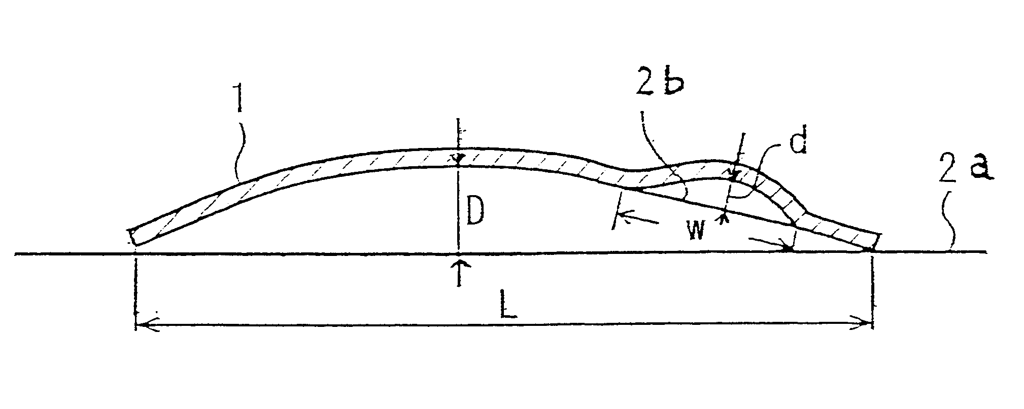
A masking layer was formed with a masking material mainly composed of a pigment and thermosetting resin instead of the low-melting glass used in Example 2. The masking material consists of a thermosetting resin composed of 30 mass % of epoxy resin mixed with 4 mass % of ethylene glycol monobutyl ether as a solvent, a mixture as a pigment of 22 mass % of lead chromate, 7 mass % of lead sulfate, and 2 mass % of lead molybdate, a mixture as a thermosetting reaction accelerator of 22 mass % of modified aliphatic polyamine resin and 3 mass % of N-butanol, and 10 mass % of diethyl glycol monobutyl ether acetate as a solvent for controlling viscosity.

A glass substrate of 2.5 mm in thickness which was the same as that used in Example 2 was heated at 545.degree. C. in a furnace where the substrate passed at a speed of 140 mm / sec and rapidly cooled by air blast at wind pressure of 20 kPa for three seconds. After that, the aforementioned masking material was screen-printed to an outer peripher...

example 6

A filter substrate was manufactured similarly to Example 5. The application of masking material and the air blast cooling treatment were conducted in the same manner as Example 5, except that the width of screen-printed area was 60 mm.

example 7

A filter substrate was manufactured similarly to Example 6. The application of masking material was conducted in the same manner as Example 6, except that the substrate was reinforced by chemical treatment in which the substrate was immersed in a melted salt of potassium nitrate (KNO.sub.3) for 4 hours, instead of being heated and, then, cooled rapidly.


PUM

PropertyMeasurementUnit
surface compressive stressaaaaaaaaaa
thicknessaaaaaaaaaa

Abstract

A glass substrate for a front filter of a display device having considerable strength and excellent display quality, and being lightweight is provided. A display device employing this display filter substrate is provided. The glass substrate has one or more of electromagnetic-wave shielding function, near infrared ray blocking function, and anti-reflection function. The glass substrate has a thickness of 1.8-3.2 mm, an average surface compressive stress of 20-70 MPa, and a warp ratio of the glass substrate of 1.0% or less. The surface compressive stress is applied by an air blast cooling process or a chemical reinforcing process. The filter substrate is disposed over a front surface of the display device.

Description

The present invention relates to a glass substrate for a filter disposed on a front surface of a display panel and, more particularly to a glass substrate suitable for a front filter of a plasma display panel (PDP). The present invention further relates to a display device provided with the substrate. It should be noted that the present invention may be applied to a field emission display (FED), a cathode ray tube (CRT) or any other display device than the PDP.RELATED BACKGROUND ARTA plasma display device is provided with a front filter having one or more function of electromagnetic-wave shielding function, near infrared ray blocking function, and anti-reflection function (high transmittance). For improving these functions, JP H11-307987A discloses a front filter substrate which has the surface resistance of 3.OMEGA. or less for the electromagnetic-wave shielding function, the transmittance of 20% or less at 850 nm wave length for the near infrared ray blocking function, and the tra...

Claims


Application Information

Patent Timeline
Patent Type & Authority Patents(United States)
IPC IPC(8): G02B5/22H01J29/86G02B1/11C03C17/00C03C17/04G09F9/00H04N5/72
CPCC03C17/007C03C17/04G02B5/226H01J29/868C03C2217/445C03C2217/452C03C2217/485C03C2218/119C03C2218/34H01J2229/8913H01J2329/869H01J2329/892G02B5/20
Inventor GODA, TAKUJIKAMISAKU, KATSUYAKUZUWA, SADAO
Owner PANASONIC CORP
Why Eureka
Try Eureka