
Test structures and methods for inspection of semiconductor integrated circuits

a technology of integrated circuits and test structures, which is applied in the direction of semiconductor/solid-state device testing/measurement, semiconductor/solid-state device details, instruments, etc., can solve the problems of increasing the time required to scan voltage contrast data to perform comparisons, adding more complexity to circuits, and requiring such small dimensions. , to achieve the effect of easy drying, improved and timely information, and convenient processing

Inactive Publication Date: 2003-03-04
KLA TEMCOR
View PDF24 Cites 63 Cited by
  • Summary
  • Abstract
  • Description
  • Claims
  • Application Information

AI Technical Summary

Benefits of technology

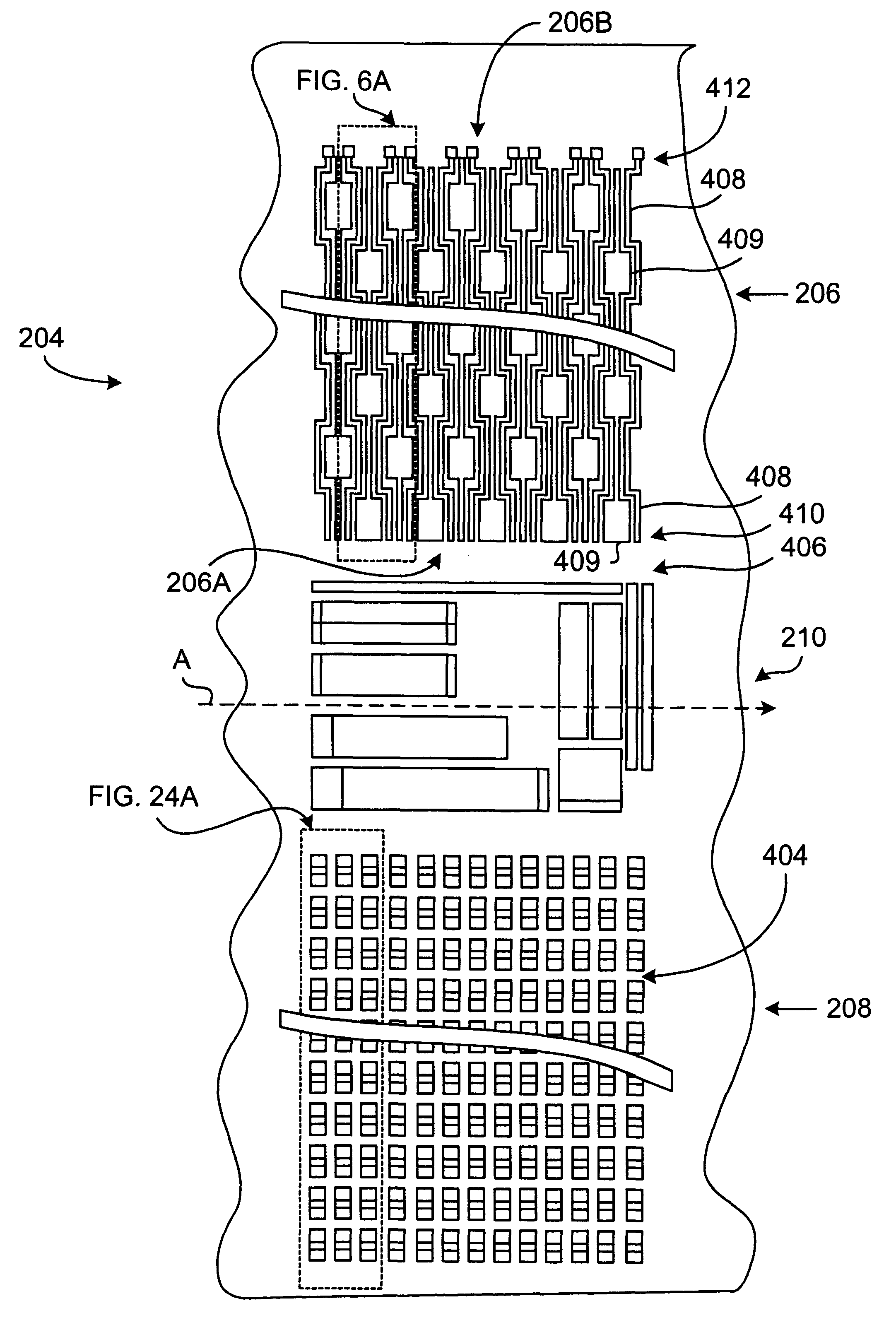
Described in this section is an exemplary test chip that is specifically designed to take full advantage of the present invention. It should be recognized, however, that the specific design described herein is exemplary only and that many other designs or configuration are possible within the scope of the present invention.
. It should be recognized, however, that the specific design described herein is exemplary only and that many other designs or configuration are possible within the scope of the present invention.
Several embodiments of the present invention are described herein in the context of exemplary multilevel integrated circuit structures, including semiconductor structures and overlying metallization or other interconnects, using various levels of conductors that are separated from each other and the substrate by dielectric layers. As is well known in the art, in such multilevel structures, a first conductor (M1) and a second conductor (M2) can be connected by vias formed through an interlayer dielectric (ILD). Similarly, contacts can be formed between the conductors and the substrate. The defect detection system of the present invention is advantageously able to detect opens, intra-layer shorts (within M1 or M2) or interlayer (between M1 and M2) shorts caused by errors occurring systematically or randomly during the manufacturing process.
In addition, specific embodiments of the present invention are also able to detect defects caused by particular process steps, such as lithographic steps, dry etch steps, deposition steps, or a chemical mechanical polishing (CMP) process. As is well known in the art, the CMP process is often used to planarize structures that build up during multilevel deposition processes. These structures can be used as damascene interconnects, conductive plugs, or for other purposes. The CMP process is expected to become even more important as the semiconductor industry shifts to copper metallization, since copper cannot be easily dry-etched (the etch products being non-volatile), but is readily processed using CMP. However, the CMP process may polish away functioning circuit parts through dishing (leading to opens) or copper smearing (leading to shorts) when the circuit layout changes drastically in density, pitch and or in the horizontal aspect ratio (length:width). The defects created by CMP process are preferably detected during the inspection process.
FIGS. 4a and 4b illustrate a semiconductor wafer 200 comprising a die array 202 that is prepared in accordance with the principles of one embodiment of the present invention. As illustrated in FIG. 4b, the array 202 may be comprised of a plurality of test dies 204 and a plurality of actual product dies 206 containing intended integrated circuitry. As will be described below, the test dies 204 allow defect location, defect identification, defect type and defect density through in-line inspections during the actual manufacturing process of integrated circuits.
The ability to detect defects in line (i.e., during the manufacturing process) is a significant advantage of the present invention. Unlike functional testing of semiconductor devices performed on completed wafers by wafer probing methods, the present invention can perform testing in line. This results in better and more timely information for the engineers controlling the manufacturing the process, and provides them with an opportunity to service machinery or alter process conditions to improve yield, before many devices are lost as scrap. By contrast, if the engineer were to wait until processing of the devices were completed, millions of dollars may be lost due to poor yield because of the delay. Moreover, the test methodologies of the present invention could be used as part of an Advanced Process Control ("APC") system, in which data from the testing process is fed to automated control systems that improve process yield with little or no human intervention, based on software algorithms that take into account the equipment and process technology used in the manufacturing process. As an example, test structures designed to detect CMP overpolish could provide data that automatically feeds back to the CMP process and causes the process to be modified such that polishing time is reduced, or pressure on the polishing pad is diminished.

Problems solved by technology

Manufacturing IC's at such minute dimensions adds more complexity to circuits and the demand for improved methods to inspect integrated circuits in various stages of their manufacture is ever present.
Although inspection of such products at various stages of manufacture is very important and can significantly improve production yield and product reliability, the increased complexity of IC's increases the cost of such inspections, both in terms of expense and time.
However, if a defect can be detected early in production, the cause of the defect can be determined and corrected before a significant number of defective IC's are manufactured.
However, considering the density of IC's currently produced, the time necessary to scan voltage contrast data to perform comparisons is significant.
The inspection and analysis of such circuits may take several days.

Method used


Image

  • Test structures and methods for inspection of semiconductor integrated circuits
  • Test structures and methods for inspection of semiconductor integrated circuits
  • Test structures and methods for inspection of semiconductor integrated circuits

Examples


Embodiment Construction

)

As will be further described below, the preferred embodiment of the present invention provides automated, rapid, contactless wafer inspection capabilities in order to detect, isolate and characterize electrical defects impacting integrated circuits.

Several embodiments of the present invention are described herein in the context of exemplary multilevel integrated circuit structures, including semiconductor structures and overlying metallization or other interconnects, using various levels of conductors that are separated from each other and the substrate by dielectric layers. However, structures formed using other methods of semiconductor fabrication also fall within the scope of the present invention.

One application of the present invention includes the operation of a scanning electron microscope (SEM) with a continuously moving stage. However, the test structures and many of the methods described herein are also useful in the context of other testing devices, including SEM's opera...


PUM

PropertyMeasurementUnit
pixel resolution sizesaaaaaaaaaa
speedsaaaaaaaaaa
widthaaaaaaaaaa

Abstract

Disclosed is a semiconductor die having a scanning area. The semiconductor die includes a first plurality of test structures wherein each of the test structures in the first plurality of test structures is located entirely within the scanning area. The semiconductor die further includes a second plurality of test structures wherein each of the test structures in the first plurality of test structures is located only partially within the scanning area. The test structures are arranged so that a scan of the scanning area results in detection of defects outside of the scanning area.

Description

1. Field of the InventionThe present invention generally relates to the field of inspection and analysis of specimens and, more particularly, to defect inspection and analysis of semiconductor integrated circuits.2. Description of the Prior ArtIn the semiconductor integrated circuit (IC) industry, there is a continuing demand for higher circuit packing densities. This demand of increased packing densities has led the semiconductor industry to develop new materials and processes to achieve sub-micron device dimensions. Manufacturing IC's at such minute dimensions adds more complexity to circuits and the demand for improved methods to inspect integrated circuits in various stages of their manufacture is ever present.Although inspection of such products at various stages of manufacture is very important and can significantly improve production yield and product reliability, the increased complexity of IC's increases the cost of such inspections, both in terms of expense and time. Howev...

Claims


Application Information

Patent Timeline
Patent Type & Authority Patents(United States)
IPC IPC(8): G01N21/66G01N21/62G01N21/956G01N21/95G01N21/88G01R31/28G01R31/307H01L23/544
CPCG01N21/66G01N21/956H01L22/34G01R31/307H01J2237/2817G01R31/2884
Inventor SATYA, AKELLA V. S.PINTO, GUSTAVO A.ADLER, DAVID L.LONG, ROBERT THOMASRICHARDSON, NEILWEINER, KURT H.WALKER, DAVID J.MANTALAS, LYNDA C.
Owner KLA TEMCOR
Learn More