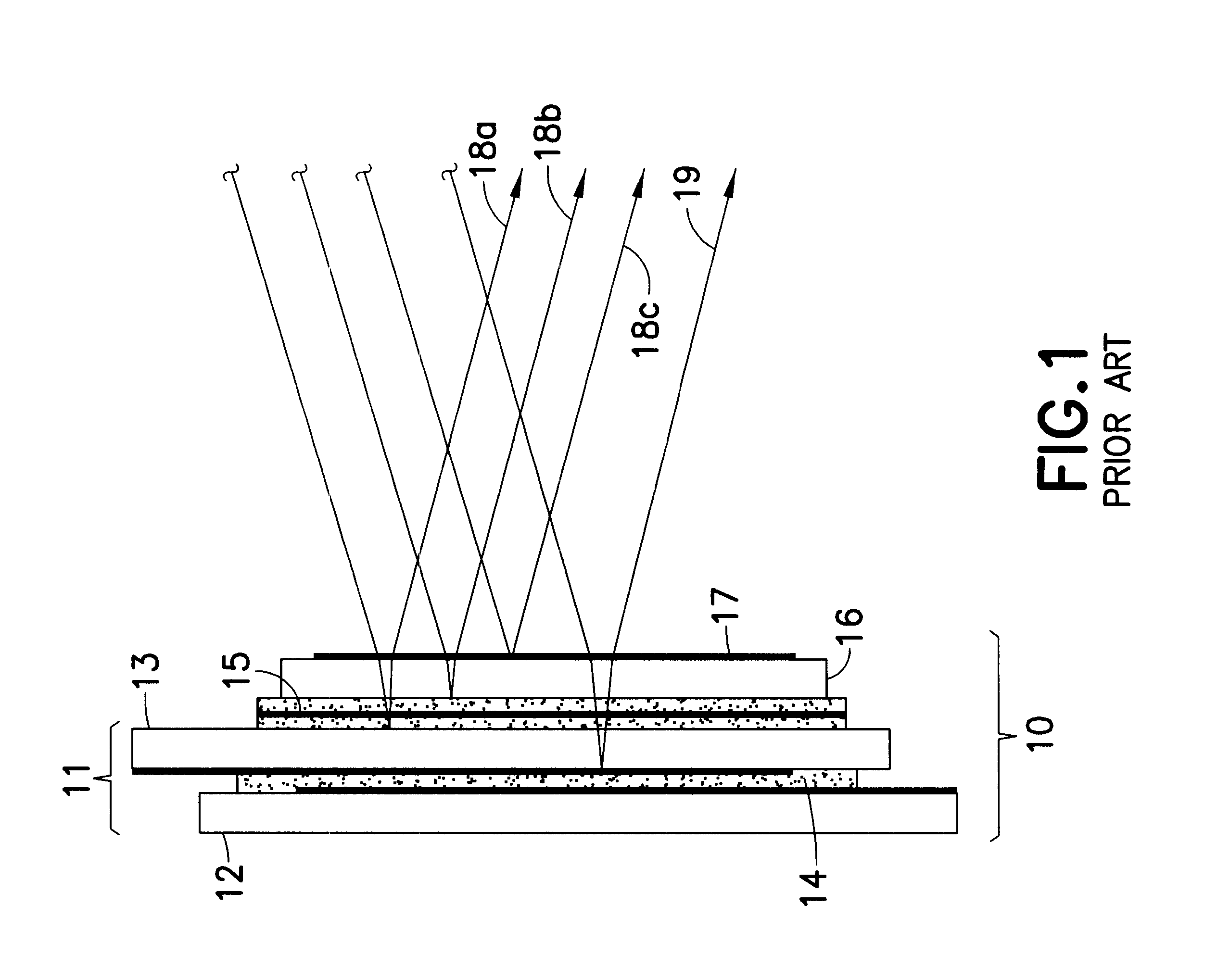
When light is incident upon a structure that exhibits reflection at two or more nearly-parallel surfaces, there is interference between beams which have reflected from the different surfaces involved, or which have experienced multiple reflections between the surfaces involved.
If the light is quasi-monochromatic or monochromatic (such as a
laser beam) and is phase-coherent over distances corresponding to the differential path lengths involved, interference will result in
spatially resolved light and dark fringes corresponding to regions of constructive and destructive interference.
However, in most imaging or modulation systems, such an interference pattern would be undesirable, and components are designed to minimize or eliminate such effects.
However, use of wedged substrates is incompatible with prevailing
liquid crystal fabrication methods, which are designed to use flat, relatively
thin sheet glass instead.
In contrast, the use of wedged substrates forces one to assemble the cells singly, at greatly increased cost.
Also, the process is considerably more labor-intensive, so the number of cells a given facility can produce is much lower than if the panelized approach is used.
Further, several of the steps involved in
liquid crystal cell fabrication--such as spin-
coating, alignment-layer buffing, and
adhesive deposition --cannot be performed as easily when wedged substrates are used, nor can comparably tight
quality control be achieved.
Thus, liquid
crystal cells that use wedged substrates are inherently more expensive, require non-standard production equipment, have lesser quality, and are difficult to provide in volume.
The quality of
coating which can be produced on glass is superior to that produced on polarizers, but even under ideal conditions it is difficult to produce less than 0.25% reflection per surface reliably.
While this is a small amount, which one might expect would have a negligible effect on the overall
assembly, this is not actually the case.
So even surfaces or interfaces that produce what one might expect to be negligible reflections, based on the reflection coefficients involved, yield quite significant interference patterns when they interfere with a bright beam.
In contrast, interference arising from parallel surfaces that are more widely spaced, will have a narrower spectral period, and will introduce
ripple or
distortion within the
passband of the
system.
Consequently, interference between such elements is more deleterious to the
system than interference across the liquid
crystal layer itself.
It is often impractical when working with relatively coherent sources (or in
narrowband instruments) to construct a liquid
crystal assembly using components that are so thick that all reflecting surfaces (or interfaces) are so far apart as to greatly exceed L. Even when possible, this approach results in excess bulk, weight, and cost.
Even if one or the other index matches that of the other components involved, it is impossible to match both.
Further, the optimum materials for
retarder selection may not have indices that are well-matched to those of the other materials.
Among other retarder materials such as liquid crystal polymers, stressed glass, KDP (
potassium dihidrogen
phosphate) and its isomorphs, some have the potential to provide a better match but all suffer one or more of the following limitations: they are not readily available, are subject to hygroscopic
attack, cannot be produced in
large aperture, have limited retardance range, or are very costly.
As this indicates, it is not practical to eliminate reflection between a retarder and a
liquid crystal cell by choice of component material.
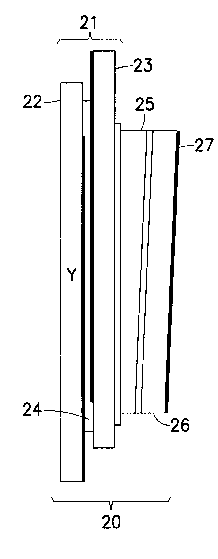
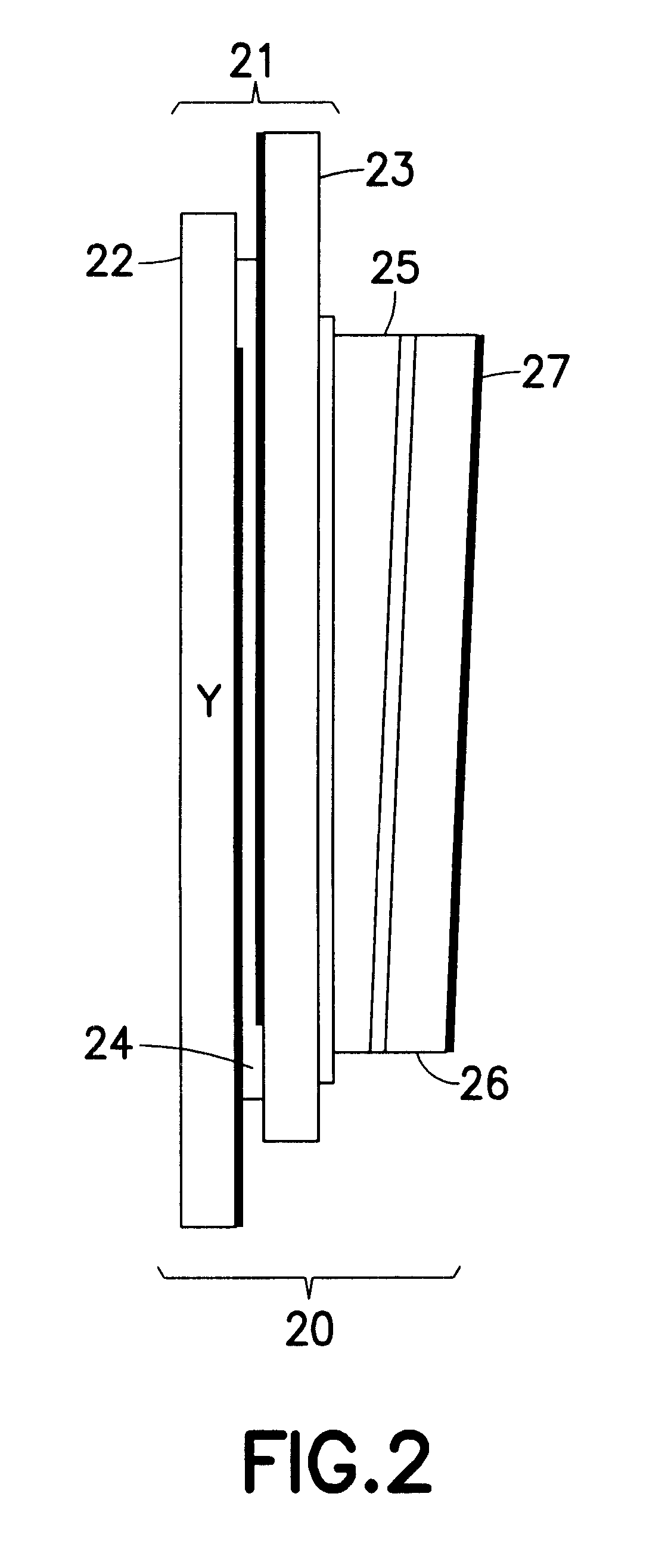
The incorporation of a retarder into the overall assembly increases the number of reflective interfaces by at least one (and in most cases two or more), and thus increases the number of interfering beams.
Consequently, all the problems recited earlier with regard to liquid crystal cells in coherent beams, apply with even greater force when constructing assemblies of liquid crystal cells with retarders.
Thus there is no device or method of construction at present which provides a
liquid crystal cell, either alone or in series with a fixed retarder, that does not suffer from significant interference between two or more beams, in addition to the interference from the opposite faces of the liquid crystal layer itself.

