
Data processing circuit, microcomputer, and electronic equipment

a data processing circuit and microcomputer technology, applied in the field of data processing circuits, microcomputers, electronic equipment, can solve the problems of reducing the efficiency with which memory is used, inefficient use of memory, and difficulty in coding instruction details within a 16-bit fixed-length

Inactive Publication Date: 2003-05-06
SEIKO EPSON CORP
View PDF24 Cites 15 Cited by
  • Summary
  • Abstract
  • Description
  • Claims
  • Application Information

AI Technical Summary

Benefits of technology

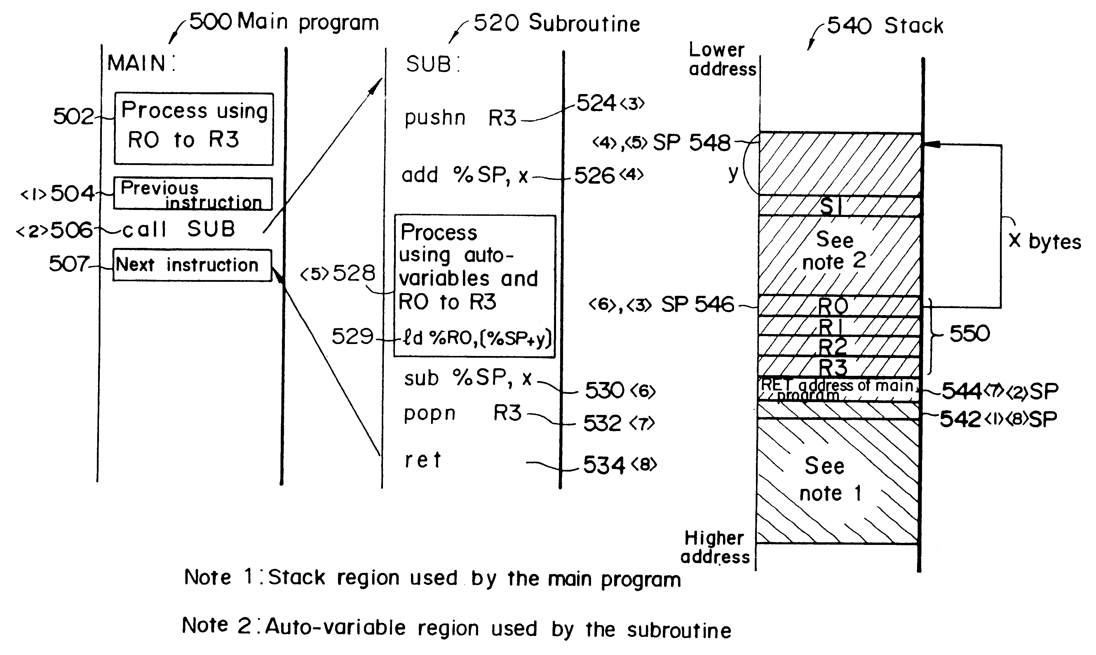
Another objective of this invention is to provide a data processing circuit, microcomputer, and electronic equipment that enables efficient coding of processes that save and restore the contents of registers, with fast processing of interrupts and subroutine calls and returns.
This aspect of the invention makes it possible to provide inexpensive, but sophisticated, electronic equipment that is facilitated by a data processing circuit that has a fast processing speed and a highly efficient usage of memory.

Problems solved by technology

Thus, if all of the instructions are written as 32-bit instructions, many of them will contain unused portions so that memory will be used inefficiently.
However, simply cutting 32-bit fixed-length instructions to fit into a fixed 16-bit length, for example, causes problems as described below.
Thus, if an instruction that acts upon a general-purpose register is used when coding a process that acts upon the stack pointer, a large amount of data has to be specified in the object code, making it difficult to code the details of the instruction within a 16-bit fixed-length.
Increasing the instruction length to 32 bits, for example, would result in a large number of instructions that do not particularly need the entire 32 bits, so that many instructions will contain unused portions, leading to a decrease in the efficiency with which memory is used.
If such push and pop instructions are used for each of the registers, the size of the object code increases and a large number of program execution steps is required, leading to delays in the execution time or processing of the program.
Disadvantages of repeating the push instruction include the increased length of program code and the delays in execution caused by executing a fetch for each instruction.
However, this is not an advantage when writing fewer than the eight registers, such as four or six registers.
In such a case, one instruction will suffice, but this gives rise to a problem in that the execution cycle of that instruction takes too long.
This leads to an increase in object code of the call and ret instructions, and the execution of a fetch for each instruction makes the execution speed sluggish.
However, this method leads to an increased instruction length, so that memory is used inefficiently.

Method used


Image

  • Data processing circuit, microcomputer, and electronic equipment
  • Data processing circuit, microcomputer, and electronic equipment
  • Data processing circuit, microcomputer, and electronic equipment

Examples


embodiment 1

(1) Configuration of the CPU of this Embodiment

The CPU of this embodiment executes virtually all of its instructions within one cycle, thanks to its pipeline and load / store architecture. All of the instructions are expressed as 16-bit fixed-length instructions, so that instructions processed by the CPU of this embodiment are implemented within compact object code.

In particular, this CPU is configured in such a manner that it has a dedicated stack pointer register to enable the efficient coding and execution of processes that act upon the stack pointer. It also enables the decoding and execution of an instruction set of a group of dedicated stack pointer instructions that have object code specifying that dedicated stack pointer register as an implicit operand.

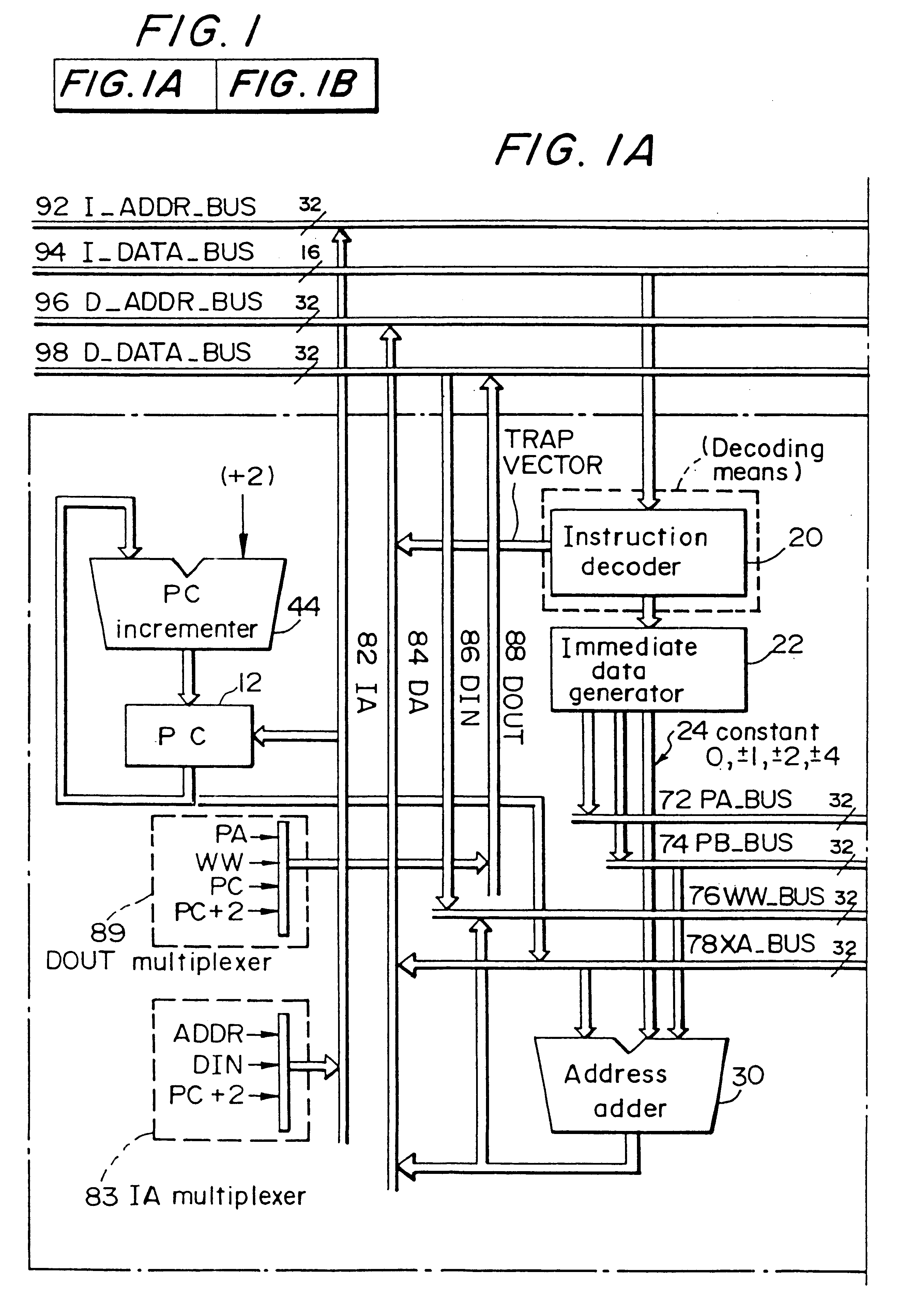
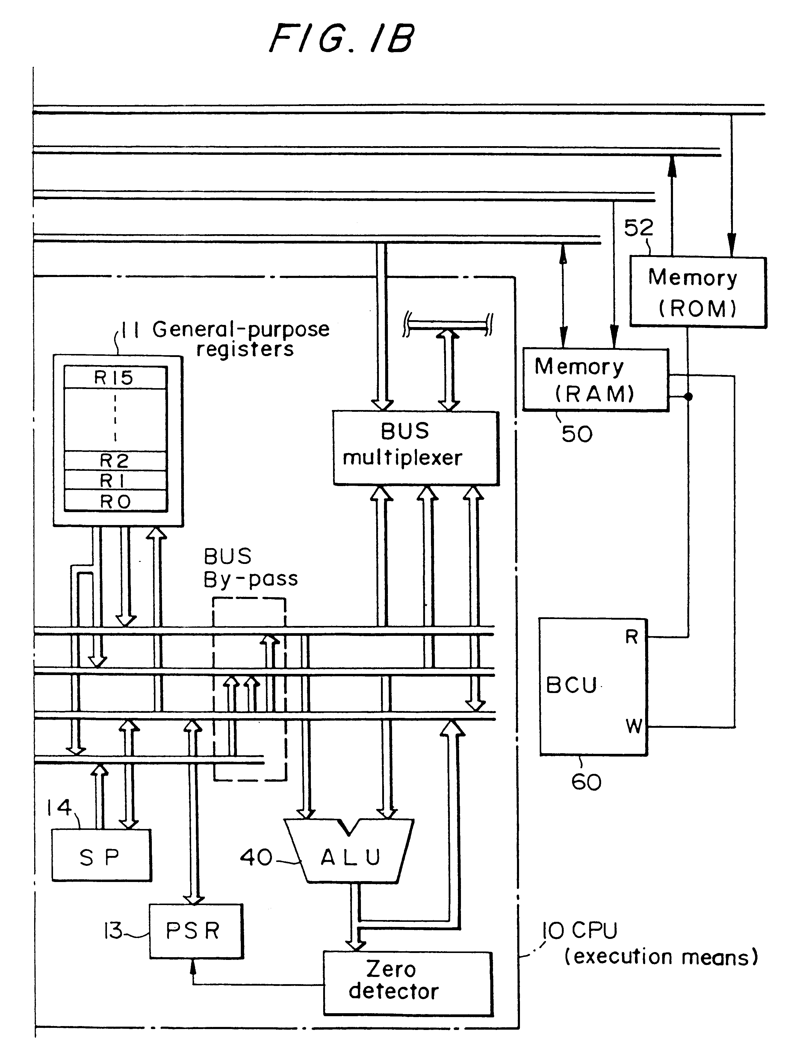
A schematic view of the circuit structure of the CPU of this embodiment is shown in FIG. 1 by way of illustration.

This CPU 10 comprises a register set that includes general-purpose registers 11, a PC register 12 for holding the ...

embodiment 2

A block diagram of the hardware of a microcomputer in accordance with this embodiment is shown in FIG. 23.

This microcomputer 2 is a 32-bit microcontroller that comprises a CPU 10; ROM 52; RAM 50; a high-frequency oscillation circuit 910; a low-frequency oscillation circuit 920; a reset circuit 930; a prescaler 940; a 15-bit programmable timer 950; a 8-bit programmable timer 960; a clock timer 970; an intelligent DMA 980; a high-speed DMA 990; an interrupt controller 800; a serial interface 810; a bus control unit (BCU) 60; an A / D converter 830; a D / A converter 840: an input port 850; an output port 860; and an I / O port 870; as well as various buses 92, 94, 96, and 98 that are connected to these components and various pins 890.

The CPU 10 has an SP that is a dedicated stack pointer register, and it decodes and executes the dedicated stack pointer instructions as described above. This CPU 10 has the same configuration as that of the previously described Embodiment 1 and it functions as...


PUM


Abstract

The data processing circuit of this invention enables efficient description and execution of processes that act upon the stack pointer, using short instructions. It also enables efficient description of processes that save and restore the contents of registers, increasing the speed of processing of interrupts and subroutine calls and returns. A CPU that uses this data processing circuit comprises a dedicated stack pointer register SP and uses an instruction decoder to decode a group of dedicated stack pointer instructions that specify the SP as an implicit operand. This group of dedicated stack pointer instructions are implemented in hardware by using general-purpose registers, the PC, the SP, an address adder, an ALU, a PC incrementer, internal buses, internal signal lines, and external buses. This group of dedicated stack pointer instructions comprises SP-relative load instructions, stack pointer move instructions, a call instruction, a ret instruction, a sequential push instruction, and a sequential pop instruction.

Description

1. Field of the InventionThis invention relates to a data processing circuit, a microcomputer incorporating this data processing circuit, and electronic equipment that is constructed by using this microcomputer.2. Description of Related ArtIn the prior art, a RISC microcomputer that is capable of manipulating 32-bit data uses fixed-length instructions that are 32 bits wide. This is because the use of fixed-length instructions enables a reduction in the time required for decoding the instructions in comparison with the use of variable-length instructions, and it also makes it possible to reduce the size of the circuitry of the microcomputer.However, even with a 32-bit microcomputer, it isn't always necessary to use the full 32 bits. Thus, if all of the instructions are written as 32-bit instructions, many of them will contain unused portions so that memory will be used inefficiently.The present inventors have investigated the idea of a microcomputer that handles fixed-length instruct...

Claims


Application Information

Patent Timeline
IPC IPC(8): G06F9/355G06F9/30G06F9/312G06F9/34G06F9/42G06F9/46G06F9/48
CPCG06F9/3004G06F9/30101G06F9/355G06F9/30167G06F9/324G06F9/30163
Inventor KUDO, MAKOTOKUBOTA, SATOSHIMIYAYAMA, YOSHIYUKISATO, HISAO
Owner SEIKO EPSON CORP
Learn More