
Canister, sealing method and composition for sealing a borehole

a technology for sealing methods and boreholes, applied in the direction of sealing/packing, borehole/well accessories, survey, etc., can solve the problems of fluid loss, cement-based materials that do not bond well to earth materials, and cannot stay in place, etc., and achieve the effect of high strength

Inactive Publication Date: 2003-05-13
TRIAD NAT SECURITY LLC
View PDF25 Cites 93 Cited by
  • Summary
  • Abstract
  • Description
  • Claims
  • Application Information

AI Technical Summary

Benefits of technology

To achieve the foregoing and other objects, and in accordance with the purposes of the present invention, as embodied and broadly described herein, there has been invented a borehole sealant for sealing, stabilizing or plugging boreholes which is ...

Problems solved by technology

Also, after casing, the elbow areas where lateral wellbores depart from the vertical hole are often the site of loss of fluids into the surrounding formation.
This fluid loss is often caused by high pressures encountered in the deviated production path, and exacerbated by mechanical failures of bonding materials at the lateral junction.
Generally, cement-based materials do not bond well to the earth materials penetrated by the borehole and often do not stay in place.
In addition, there are often problems getting these materials applied at precisely the desired depths and adapted to the particular downhole conditions in the trouble zone, particularly in severe lost circulation situations where cement materials tend to be overdisplaced away from the near-wellbore region.
Further, with cement-type materials there can be difficulty judging appropriate pumping times and setting times at the elevated temperatures that are encountered in geothermal or very-deep petroleum drilling situations.
Furthermore, if the formation or fracture zone is severely underpressured or the formation contains large open porosity (e.g., interconnected large solution cavities in limestone formations), sealing the trouble zone by injecting cement from the surface is often unsuccessful.
It is often unsuccessful no matter how many times the sealing operation is repeated because the hydrostatic head of the cement slurry causes the cement to be overdisplaced (i.e., carried away) from the near-wellbore region where the sealing is desired.
However, fibrous lost-circulation materials being carried in the drilling fluid may not adequately bridge-off the fractures or fill the open porosity because of the large outward pressure gradient from the overpressured borehole into the severely underpressured formation.
However, since portland cement does not adhere well to most geologic materials, the typical result is to "wash" the cement out of the borehole and cavity while redrilling.
Similarly, when swelling clay (hydrating) formations are encountered in drilling, the standard remedial approach is to prevent water-based fluids from penetrating or reacting with the clays and causing swelling by: (a) forming an impervious "wall cake" on the wall of the borehole; or (b) adding potassium chloride to the drilling fluid to make it less reactive with the clays; or (c) switching to a hydrocarbon-based drilling fluid, which is, however, generally undesirable because of increased costs, difficulties of cleanup and environmental hazards.

Method used


Image

  • Canister, sealing method and composition for sealing a borehole
  • Canister, sealing method and composition for sealing a borehole
  • Canister, sealing method and composition for sealing a borehole

Examples


example i

In a bench top demonstration of an invention slurry and sealant, a slurry was mixed and allowed to set up in a beaker filled with water.

An invention slurry was prepared by combining a total of 200 g of class-F fly ash, calcined magnesium oxide and monopotassium phosphate in a 60:9:31 ratio. The 200 g mixture was stirred in 20 g of water for about 20 minutes. The slurry had started reacting and had formed a thick paste. The thickened slurry was then poured into a beaker and allowed to set for about 60 minutes.

After the slurry had solidified, hot water at a temperature of 90.degree. C. was poured onto the set slurry. The beaker was maintained at 90.degree. C. on a hot plate for about 30 minutes. The slurry did not dissolve or react in the water.

Then 220 g of a second slurry was prepared in the same manner as the first slurry with the same ratio of components.

After about 30 minutes the second slurry had started to react and thicken. The second slurry was poured into the hot water in th...

example ii

In another bench top demonstration of the invention, setting time as a function of temperature was measured.

A 220 g portion of slurry was prepared in the same manner as the slurries in Example I and in the same proportions of components. The beaker in which the slurry was prepared was then lowered into a water bath maintained at a temperature of 60.degree. C. and the time of setting was measured by determining the time that the slurry took to form a hardened monolith.

The procedure was repeated at temperatures of 70.degree. C., 80.degree. C., and 90.degree. C. Each time the setting time was measured. Setting times decreased as temperatures increased, ranging from a setting time of about 70 minutes at 60.degree. C. to a setting time of about 35 minutes at 90.degree. C. The results of this test of an invention slurry are shown in the graph of FIG. 9.

example iii

An invention slurry prepared in the same manner as that prepared in Example I and having the same ratio of components was poured into polyethelene beakers containing sandstone, limestone and granite rocks. The rocks were several inches in size and of the sort typically found in oilfield drilling environments.

The slurry in each of the beakers was allowed to set for a day, during which time it formed into monoliths with the rocks as inclusions. The monoliths were removed from the beakers.

A diamond tipped saw was used to cut the monoliths into cross sections. In each case the slurry had formed into a sealant which encapsulated the rocks with no gaps at the interface between the rock surfaces and the slurry. In fact, the slurry had penetrated into the pores in the surfaces of the rocks forming a tight bond and excellent seal with the rocks. A cross section of this is shown in the photograph of FIG. 10.

While the methods and compositions of this invention have been described in detail for...


PUM

PropertyMeasurementUnit
Volumeaaaaaaaaaa
Strengthaaaaaaaaaa
Circumferenceaaaaaaaaaa

Abstract

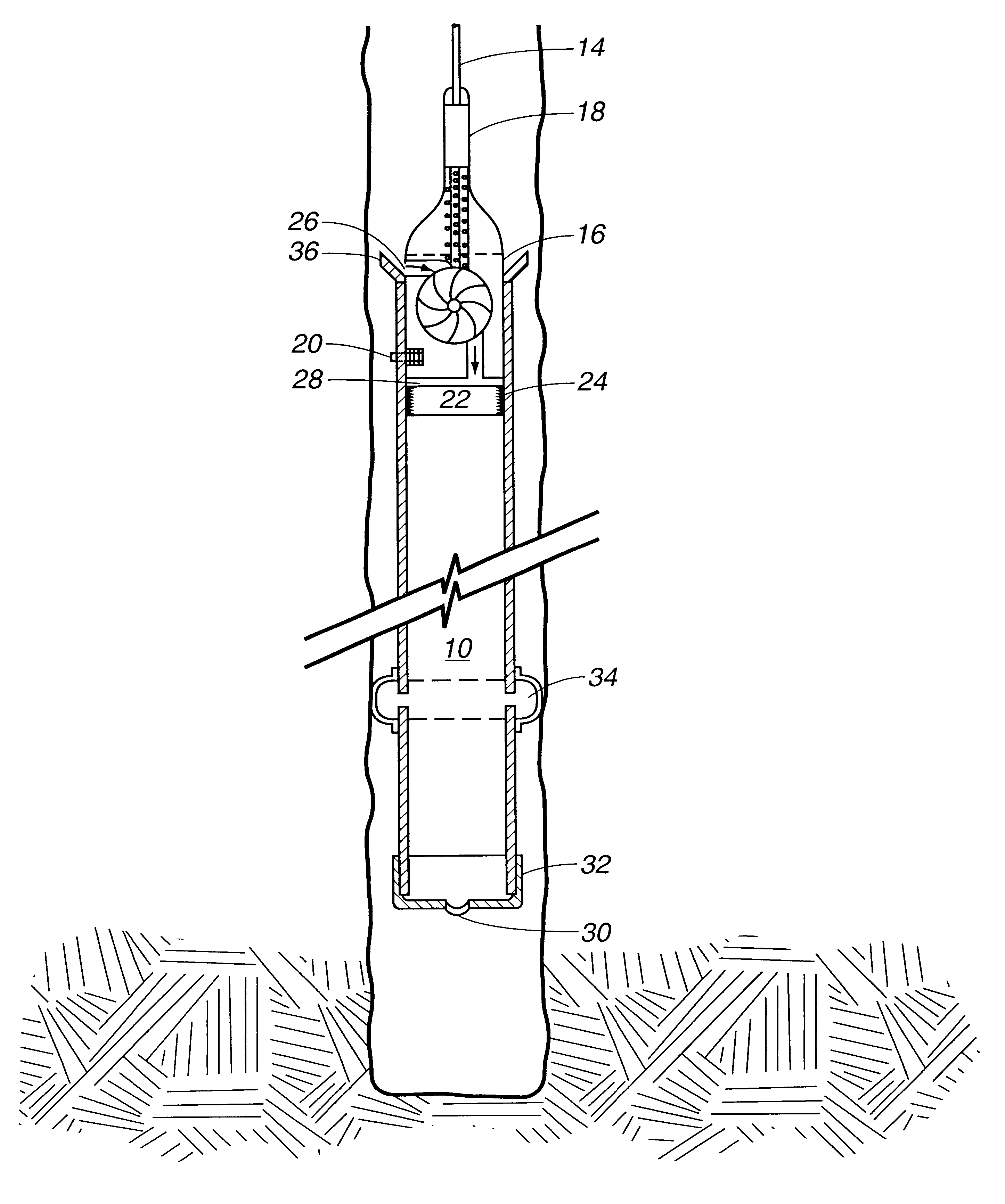
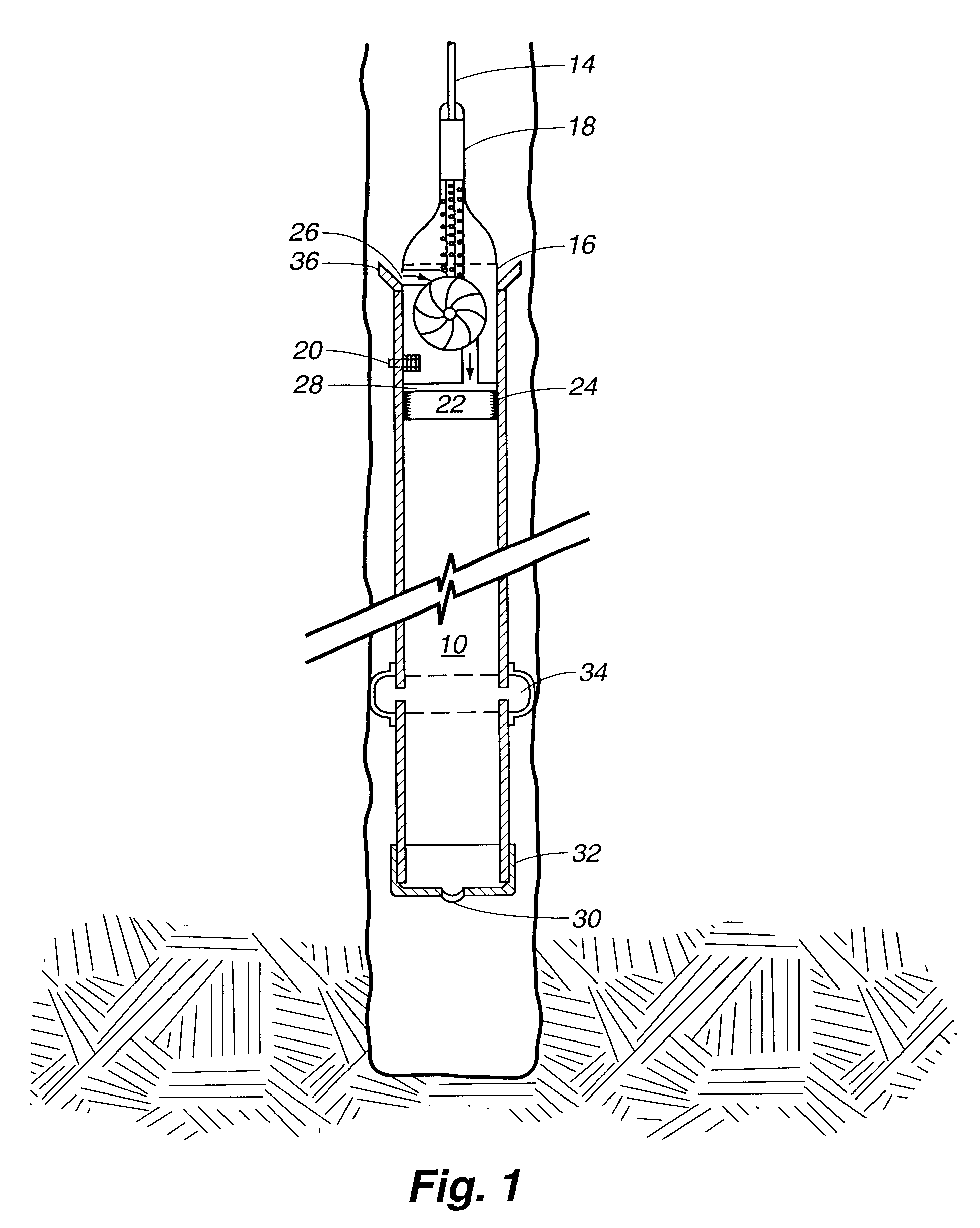
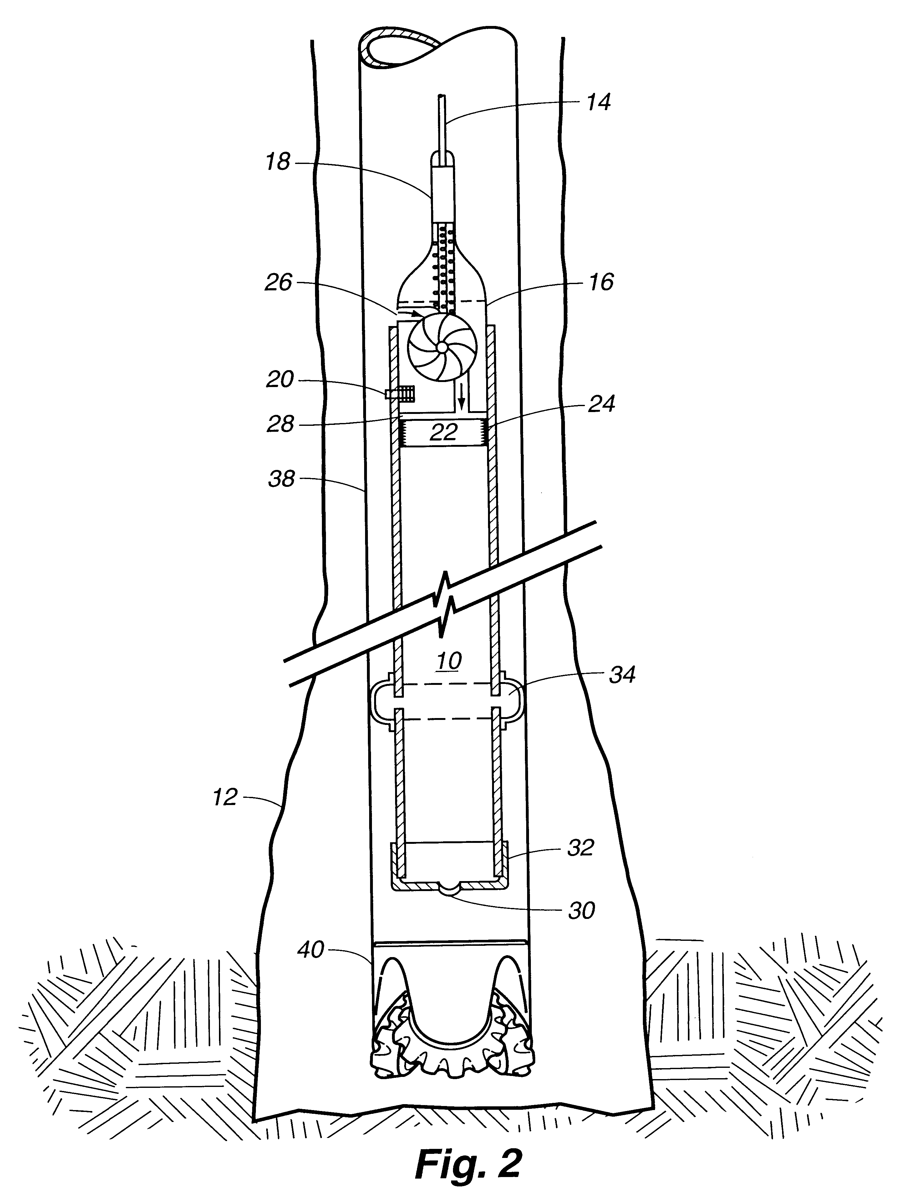
Canister, sealing method and composition for sealing a borehole. The canister includes a container with slurry inside the container, one or more slurry exits at one end of the container, a pump at the other end of the container, and a piston inside that pushes the slurry though the slurry exit(s), out of the container, and into a borehole. An inflatable packer outside the container provides stabilization in the borehole. A borehole sealing material is made by combining an oxide or hydroxide and a phosphate with water to form a slurry which then sets to form a high strength, minimally porous material which binds well to itself, underground formations, steel and ceramics.

Description

This invention relates to methods of sealing or stabilizing boreholes and compositions for sealing or stabilizing boreholes.This invention was made with government support under Contract Nos. W-7405-ENG-36 and W-31-109-ENG-38 awarded by the U.S. Department of Energy. The government has certain rights in the invention.When holes are being drilled for exploration, rock and soil sampling, water, oil, gas, or geothermal developments, there is often a need to seal or stabilize the walls of the borehole, cement in casing pipes, or seal portions of the well at some depths while other portions at other depths are treated or produced. Drilling programs for multilateral, horizontal or deviated wells often require that portions of a wellbore be sealed or plugged. Also, after casing, the elbow areas where lateral wellbores depart from the vertical hole are often the site of loss of fluids into the surrounding formation. This fluid loss is often caused by high pressures encountered in the deviat...

Claims


Application Information

Patent Timeline
IPC IPC(8): C04B28/00C04B28/34C09K8/42C09K8/46E21B27/00E21B33/13E21B27/02
CPCC04B28/34C09K8/46E21B27/02E21B33/13E21B41/0042C04B14/04C04B20/002C04B20/0048C04B22/0026C04B41/53C04B2111/00301C04B2103/20
Inventor BROWN, DONALD W.WAGH, ARUN S.
Owner TRIAD NAT SECURITY LLC
Learn More