Battery system

a battery and system technology, applied in the field of batteries, can solve the problems of long expected discharge time of such batteries for underwater vehicles, large amount of energy, and pure hp implies a handling risk, and achieve the effect of quick mechanical charging and high utilization of reactants

Inactive Publication Date: 2003-06-03
DEN NORSKE STATS OLJESELSKAP AS +1
View PDF11 Cites 29 Cited by
  • Summary
  • Abstract
  • Description
  • Claims
  • Application Information

AI Technical Summary

Benefits of technology

are a battery with high utilization of the reactants combined with the possibility of quick mechanical charging.
b) The concentration of oxidant can be kept high, which makes high current densities on the cathode possible.

Problems solved by technology

Expected time of discharge for such a battery for an unmanned underwater vehicle is long, typically more than 10 hours.
Pure HP implies a handling risk, as HP is unstable and the decomposition of HP releases a considerable amount of energy.
Liquid oxygen, LOX, provides effective storage based on weight, but cryogenic storage of oxygen demands a certain thickness of the isolation, so that one for small systems gets very voluminous tanks in relation to the useful volume.
Further, a cryogenic storage tank is basically not suitable at large external pressures.
For this reason, the storage in a UUV has in practice to be carried out in a pressure tank, which makes the system not very well suited for application in small vehicles.
Traditional metal tanks are heavy, typically an empty weight of 15 kg can store 4 kg oxygen, but fibre reinforced tanks can be made considerably lighter, and a storage capacity of 40-50% is not unlikely in the future.
This is a considerable problem for UUV's which are to operate at great depths.
Even if the solubility increases proportionally with pressure, the rate of dissolution is relatively slow, which can entail a complex system for the mixing of oxygen into the electrolyte.
A problem with batteries where the oxidant is dissolved in the electrolyte is that the oxidant and anode metal can be consumed by direct reaction with each other.
These non-current-producing reactions lead to losses of reactants and subsequently to reduced energy output from the cell.
Further, they lead to an undesired heat generation in the cell.
By sufficiently high reactivity, the rate of reaction will be limited by the transport of oxidant to the anode surface (limiting current conditions).
Unfortunately, in a real system, a substantially lower charge density is obtained.
This is partly due to the fact that the entire alkaline electrolyte cannot be consumed, and partly due to parasitic reactions which lead to the consumption of reactants (corrosion reactions).
a) Low losses of capacity by direct reaction between oxidant and anode.
b) The concentration of oxidant can be kept high, which makes high current densities on the cathode possible.
c) Solid particles in the anolyte (such as Al(OH).sub.3) does not affect the cathode reaction. while the disadvantages ar
d) Complicated structure of the cells with separate circuits for anolyte and catholyte.
e) The membrane contributes to the ohmic losses in the battery.
f) Membranes are not very mechanically robust.
This leads to demands for easy disassembling and leak proof operation which can be difficult to satisfy.

Method used


Image

  • Battery system
  • Battery system
  • Battery system

Examples


Embodiment Construction

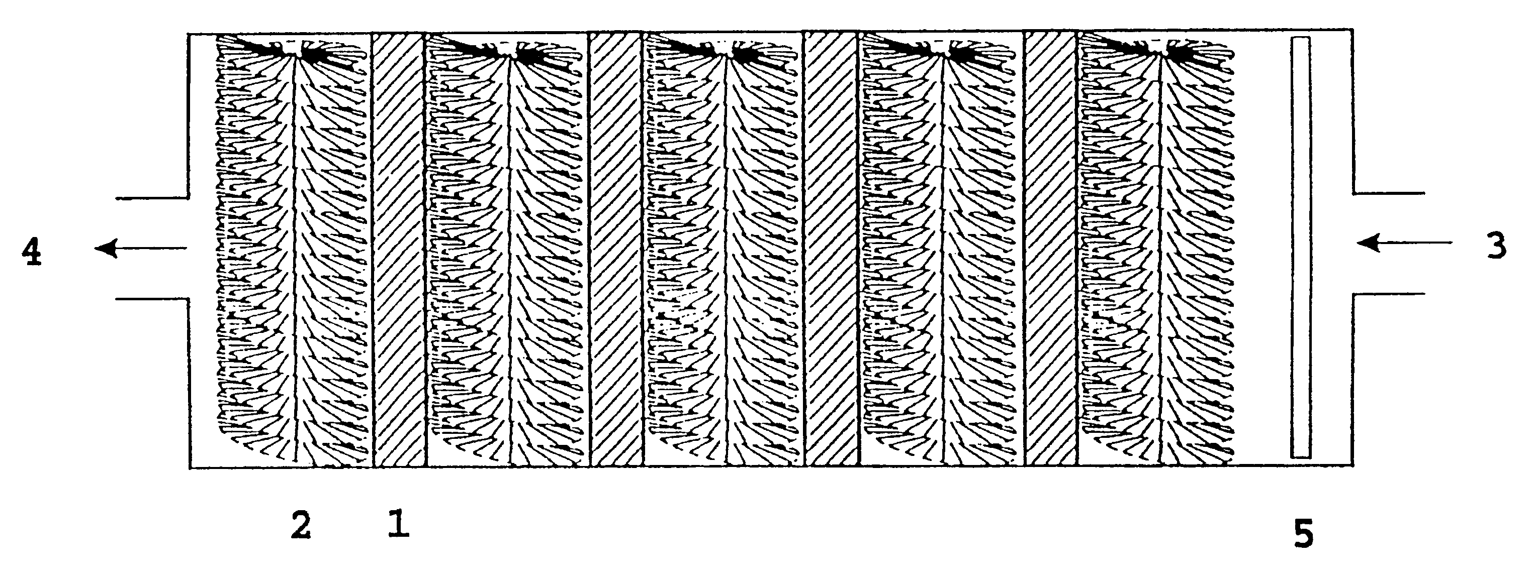
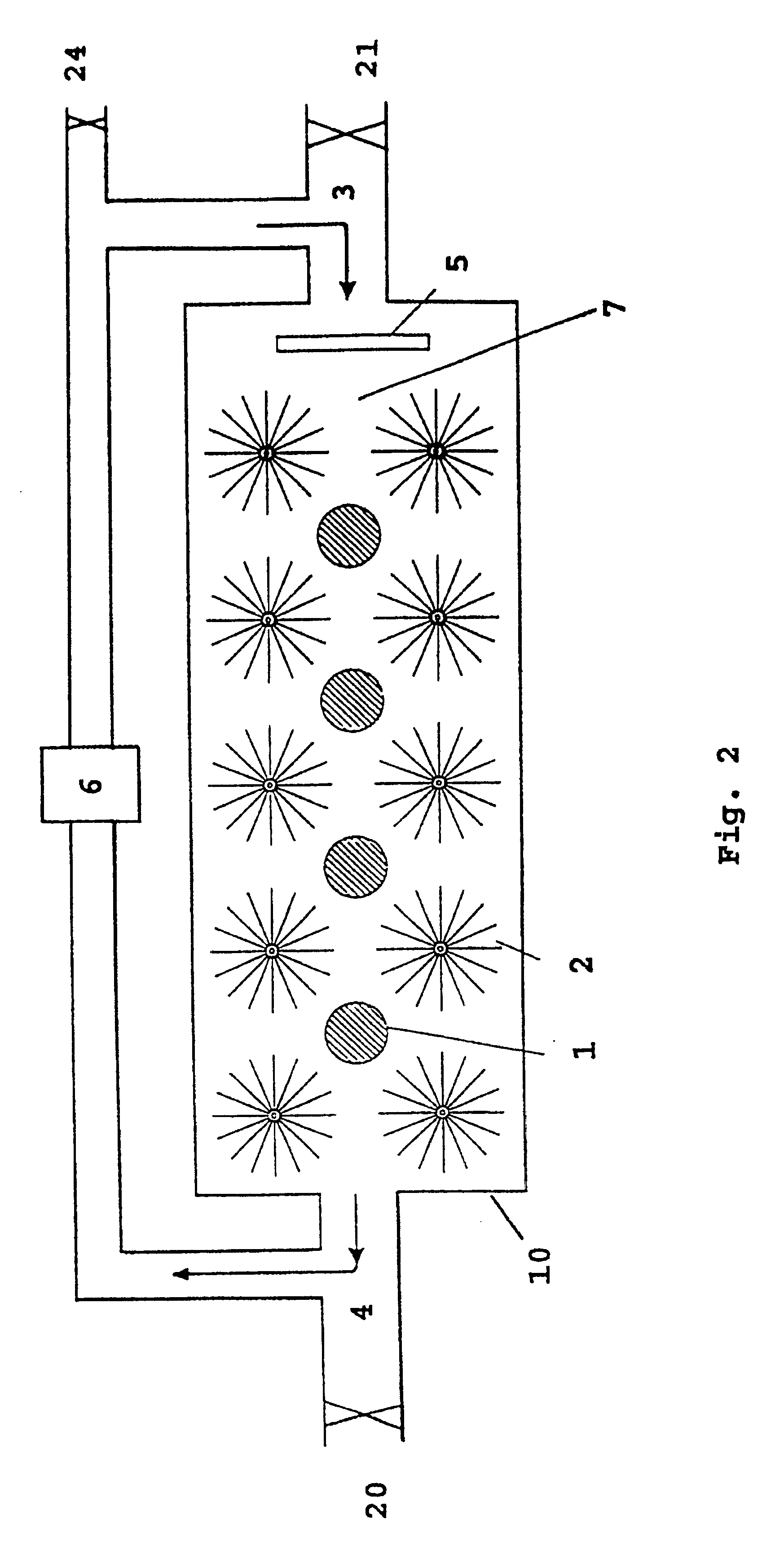
FIG. 2 shows the main features of a cell 10 with anodes 1 and cathodes 2 in an electrolyte 7. The cell produces electric energy by the reaction between hydrogen peroxide or oxygen, and aluminium or lithium or a mixture thereof, and hydroxyl ions in water. Cathodes 2 are cylindrical and based on radially oriented carbon fibres attached to a stem of metal. Anodes 1 and cathodes 2 are arranged in a flowing electrolyte 7 of KOH or NaOH dissolved in water, and with the electrolyte 7 containing the oxidant in low concentration.

Pump means 6 is adapted to pump electrolyte 7 from an electrolyte outlet 4 in the cell 10 to an electrolyte inlet 3 in the same cell. In a preferred embodiment, there is arranged an electrolyte distributor 5 after inlet 3 on cell 10, which causes the electrolyte 7 to be distributed as evenly as possible across the cross section of cell 10.

For a battery containing several cells, the electrolyte can move from cell to cell (serial flow) or parallel via in-and outlet ma...


PUM

PropertyMeasurementUnit
time of dischargeaaaaaaaaaa
weightaaaaaaaaaa
weightaaaaaaaaaa

Abstract

The present invention relates to a cell for the production of electric energy by reaction between hydrogen peroxide or oxygen, and aluminium or lithium or a mixture thereof, and hydroxyl ions in water, where the cathodes are cylindrical and based on radially oriented carbon fibres attached to a stem of metal. The novel feature of the invention is that by utilizing such cathodes in a cell with circulating electrolyte, it is possible to keep the concentration of oxidant in the electrolyte low and thus obtain high utilization of the reactants.

Description

The invention relates to a battery for the production of electric energy by reaction between hydrogen peroxide (H.sub.2 O.sub.2) or oxygen, and aluminium or lithium or a mixture thereof, and which utilizes electrodes of bottle brush shape, and which can mechanically be charged by inserting metal anodes. The advantages of the invention are a battery with high utilization of the reactants combined with the possibility of quick mechanical charging.The main object of the invention is a battery which can be utilized for the energy supply of small unmanned underwater vehicles (UUV), but the invention is not limited for this use only. The battery is going to have pressure-compensated operation, i.e. the battery does not have to be encapsulated in a pressure tank. The cells are based on an alkaline electrolyte with H.sub.2 O.sub.2 or oxygen as the oxidant, and metal anodes. The oxidant is added to the electrolyte, and the electrolyte is pumped through the cells in the battery. The anode mat...

Claims


Application Information

Patent Timeline
Patent Type & Authority Patents(United States)
IPC IPC(8): H01M12/06H01M12/04H01M12/00H01M4/70H01M4/75
CPCH01M12/06H01M12/04H01M4/75Y02E60/10
Inventor HASVOLD, .O SLASHED.ISTEIN
Owner DEN NORSKE STATS OLJESELSKAP AS
Why Eureka
Try Eureka