Convertible blood clot filter
a clot filter and vena cava technology, applied in the field of clot filter, can solve the problems of affecting the quality of blood clot filter, and causing bleeding complications for patients, so as to eliminate the associated risk, reduce the risk of patient morbidity and mortality, and achieve effective caval filter
- Summary
- Abstract
- Description
- Claims
- Application Information
AI Technical Summary
Benefits of technology
Problems solved by technology
Method used
Image
Examples
second embodiment
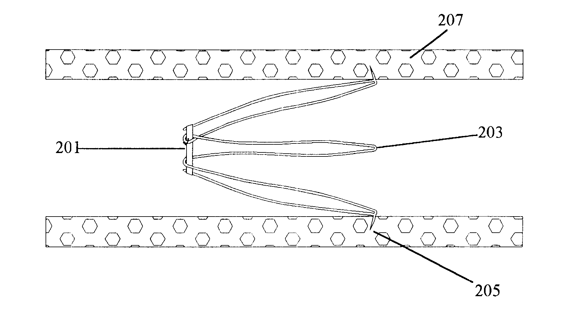
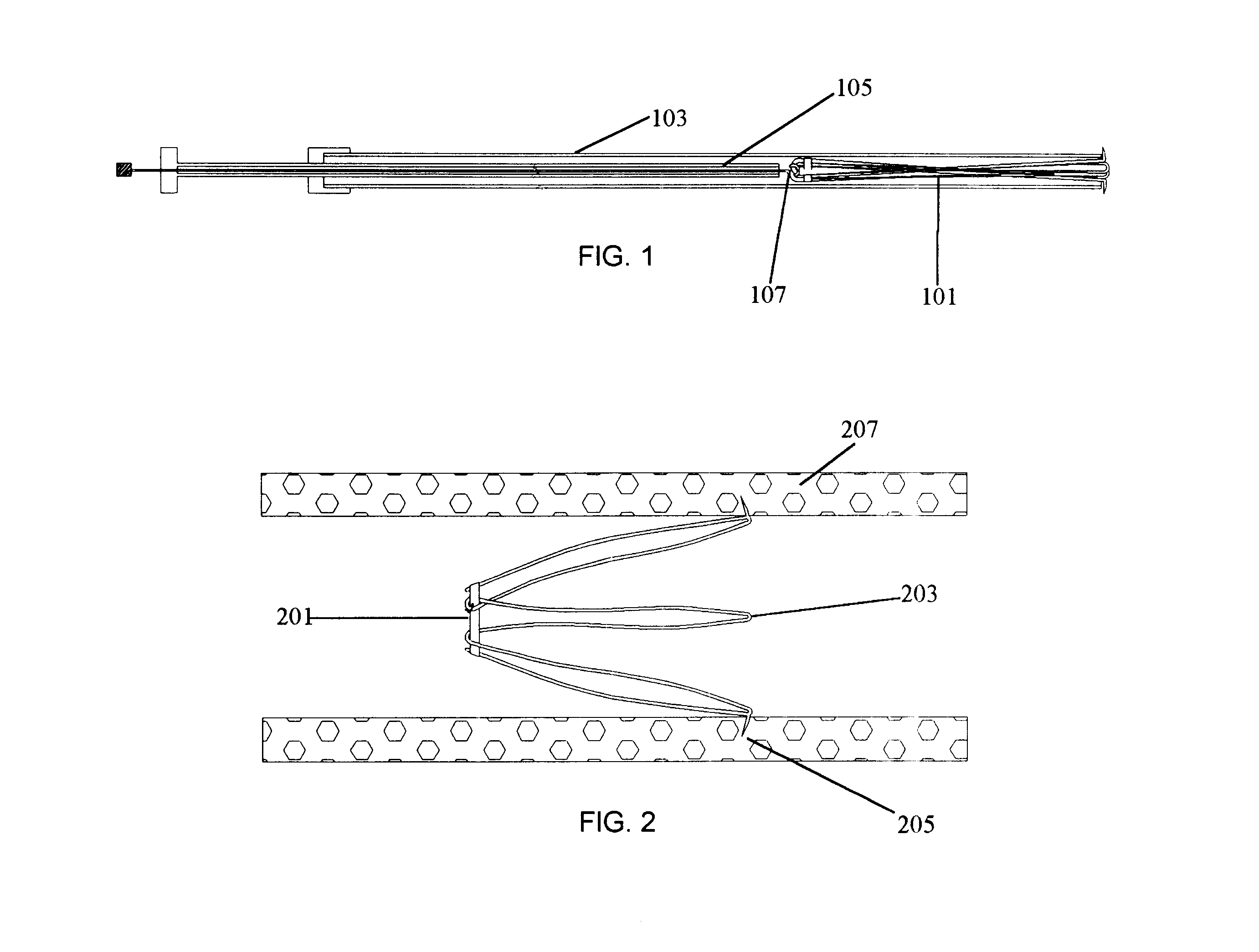
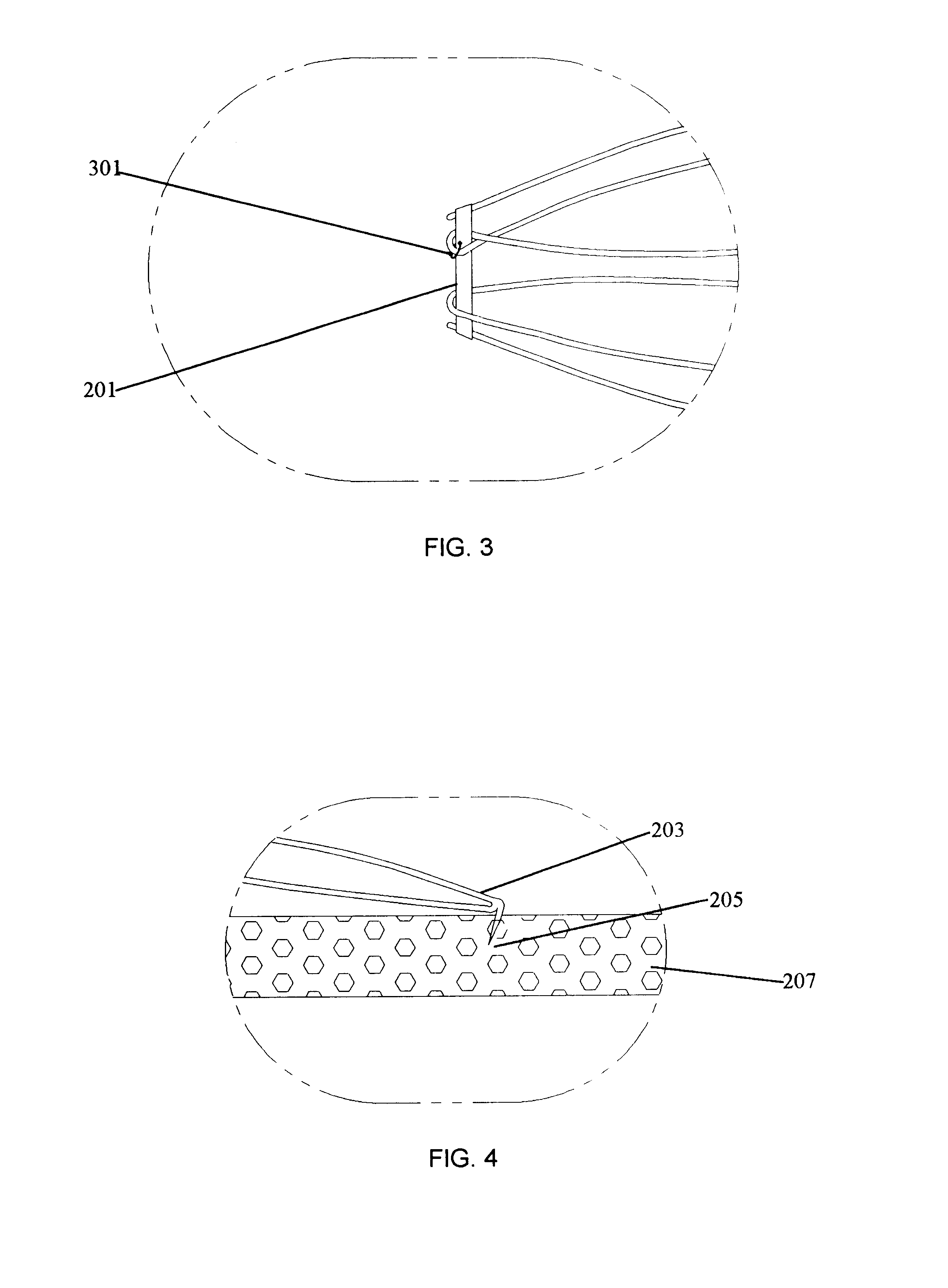
FIGS. 9A-9B depict the present invention. Filter 101 is presented in its deployed form. Ring 201 retains the narrow end of the filter 101 in its conical shape and is intertwined with the wire of the filter such that the ring will not be dislodged from the filter body. Ring 201 is shown as a tied suture. Tie 301, however, is not connected to the filter 101. Not connecting the ring 201 to the filter 101 via tie 301 allows the ring 201 to be completely removed after the ring 201 has been broken.
FIGS. 10A and 10B depict a modification of the second embodiment that uses a unitary ring 201, rather than a tied suture, to contain the conical end of the filter 101. The unitary ring 201 is slid over the barbed end by weaving it over and under alternating leg sets. The ring is slid fully to the opposite end where it remains in position holding the conical end of the filter in the constrained position. The advantage of this simple unitary ring is there is no knot that can be prone to premature ...
third embodiment
FIGS. 12 and 13 depict the present invention. Filter 101 is composed of two pieces, the base section 1201 and the filter section 1203. The base section 1201 is cylindrical in shape and completely lines the walls of the cava vena. Barbed anchors hold the base section in place against the caval wall.
The filter section 1203 is shaped into a cone and has a hooked portion 1205 at the end of each leg 1203. This hooked portion 1205 will engage with corresponding bends in the wire of the base section 1201. The blood flow will push the hooked portions 1205 against the bent wire to hold the filter section 1203 connected to the base section 1201. At the apex of the cone, a disengaging hook 1207 is placed.
To disengage the filter section 1203 from the base section 1201, a removal device 1301 is inserted. The removal device 1301 can have a hook 1303 contained within an outer tube 1305. The removal device is maneuvered over the disengaging hook 1207 of the conical filter section 1203. When inserte...
fourth embodiment
FIGS. 14 and 15 depict the present invention. Similar to the third embodiment, the filter 101 is composed of two pieces, the base section 1401 and the filter section 1403. Legs 1405, however, contain weakened sections that are predisposed to be broken when desired. The weakened sections can be designed to be broken by the application of a low voltage electrical current or be a physically weaker substance. FIG. 15 depicts the removal device to be used for the fourth embodiment in which hook 1503 engages disengaging hook 1407 and filter section 1403 breaks off at predetermined weakened sections 1409. Once completely broken off, the filter section 1403 can be retracted into the removal device and extracted from the patient.
FIGS. 16 and 17 depict yet another embodiment of the present invention. Filter 101 is composed of a single wire structure and shaped in the form of a cone to filter the blood stream. At the narrow end of the filter, the apex of each return bend is shaped in a loop of...
PUM
 Abstract
Description
Claims
Application Information
 - R&D
- Intellectual Property
- Life Sciences
- Materials
- Tech Scout
- Unparalleled Data Quality
- Higher Quality Content
- 60% Fewer Hallucinations
Browse by: Latest US Patents, China's latest patents, Technical Efficacy Thesaurus, Application Domain, Technology Topic, Popular Technical Reports.
© 2025 PatSnap. All rights reserved.Legal|Privacy policy|Modern Slavery Act Transparency Statement|Sitemap|About US| Contact US: help@patsnap.com


