Spindle apparatus

a spindle and shaft technology, applied in the direction of piston pumps, positive displacement liquid engines, milling machines, etc., can solve the problems of indefinite quantity of lubricating oil to be supplied to the interior portion of the bearing, the torque of the bearing and the temperature of the bearing can vary, and the operation environment is worse, so as to reduce the generation of noise, reduce the generation of torque and bearing, and reduce the effect of torque and bearing increas

Inactive Publication Date: 2003-09-23
NSK LTD
View PDF26 Cites 35 Cited by
  • Summary
  • Abstract
  • Description
  • Claims
  • Application Information

AI Technical Summary

Benefits of technology

to provide a lubricating device which injects a high-precision set fine quantity of lubricant onto the lubricating surface of a rotary body at a high speed to thereby minimize an increase in torque and bearing temperature so as to be able not only to provide high torque stability and reduce the generation of noises but also to reduce the size and cost thereof, and a spindle apparatus using such lubricating device.
Also, in case where a cut-out groove for arrangement of the pipe is formed in the insertion portion of the second inner housing, when the first housing is slid in the axial direction, the pipe can be stored in the cut-out groove, so that the pipe can be inserted smoothly.

Problems solved by technology

Firstly, in the lubricating device of an oil mist type, due to use of the compressed air, not only there arises a noise problem but also the mist-like lubricating oil scatters into the air to worsen an operation environment. Also, because of the scattering of the mist-like lubricating oil into the air, the quantity of lubricating oil to be supplied to the interior portion of the bearing is indefinite. Especially, in case where the bearing is rotated at a high speed, due to the effect of an air curtain, when dm.multidot.N is equal to or larger than 2000000 (dm expresses the pitch circle diameter of the bearing (mm), and N expresses the rotation speed (min.sup.-1) of the bearing), the lubricating oil can be little supplied to the interior portion of the bearing, thereby raising a fear that the bearing can cause seizure.
In the lubricating device of an oil-air type, similarly to the above-mentioned oil mist type lubricating device, since the compressed air is used, not only there arises a noise problem but also the mist-like lubricating oil scatters into the air to thereby worsen the operation environment.
Therefore, similarly, the lubricating oil can be little supplied to the interior portion of the bearing, thereby raising a fear that the bearing can cause seizure.
Also, in the lubricating device of an oil-air type, because it is difficult to supply a fine amount of lubricating oil continuously and stably, the lubricating oil must be supplied intermittently and thus the lubricating oil is supplied at a given quantity (normally, in the range of 0.01-0.03 ml) every given interval time (normally, in the rage of 8-16 min.) into the air pipe.
Therefore, since the quantity of lubricating oil to be supplied to the interior portion of the bearing varies every given time, the lubricating condition of the interior portion of the bearing varies all the time and, especially, just after the lubricating oil is supplied, a large quantity of lubricating oil enters the interior portion of the bearing, thereby causing a phenomenon that the torque of the bearing and the temperature of the bearing can vary.
There is a fear that this phenomenon can have ill effects on the working precision of a machine tool.
On the other hand, in a lubricating device of a jet type, when compared with the above lubricating devices of oil mist and oil-air types, there is little found the effect of the above-mentioned air curtain but, not only because there is required an attendant device such as a high-pressure pump but also because the quantity of lubricating oil to be supplied to the bearing increases to thereby increase drag resistance, there is necessary a large motor which is used to drive the spindle, which results in the increased cost.
However, in the above-mentioned pump using a giant magnetostrictive material or flow control valve, there are found the following problems.
The fine fixed quantity liquid supply device disclosed in Japanese Patent Examined Publication No. 2-15003 of Heisei has not solved yet a drawback caused by delivering the lubricant to the nozzle using the high-pressure air.
As a result of this, a device using such coil increases in size.
However, in the conventional oil-air lubricating method, there are dimensional limits, for example, the sizes of sealing parts such as an O-ring and the size of a return spring, which makes it difficult to reduce the diameter and stroke of the piston.
For this reason, it has been believed difficult to discharge a quantity of less than 0.01 ml of lubricating oil.
15 min., thereby raising a problem that the temperature of the constantly rotating bearing can pulsate at the oil shot intervals.
This raises a problem even in the case of a spindle which does not rotate at a very high speed, that is, when the product (dm.multidot.N) of the shaft diameter [mm] and the shaft rotation speed [min.sup.-1 ] is 1500000 or less.
However, in the case of a fine quantity of lubricating oil being supplied, in a pipe arrangement structure using such O-rings 104, when the lubricating oil is jetted out, the volume of the interior portion of the pipe passage is caused to vary due to the elastic deformation of the O-rings 904, which makes it impossible to supply a given quantity of lubricating oil.
Moreover, since compressed air supplied by a compressor is not used as in the lubricating device of an oil mist system or an oil-air system, the noise level is low and the oil mist can be little produced.
On the other hand, in case where the current value measured at the time when a certain time has passed after the start of the supply of the current is smaller than the design value, that is, in case where the time required for the current to increase up to a certain current value is longer than the design value, it can be judged that an abnormal condition such as lubricant leakage has occurred.
That is, in case where the oil discharge quantity is very small, it is difficult to deflate the air within the pipe only by repeating normal oil dischargings.

Method used


Image

  • Spindle apparatus
  • Spindle apparatus
  • Spindle apparatus

Examples


first embodiment

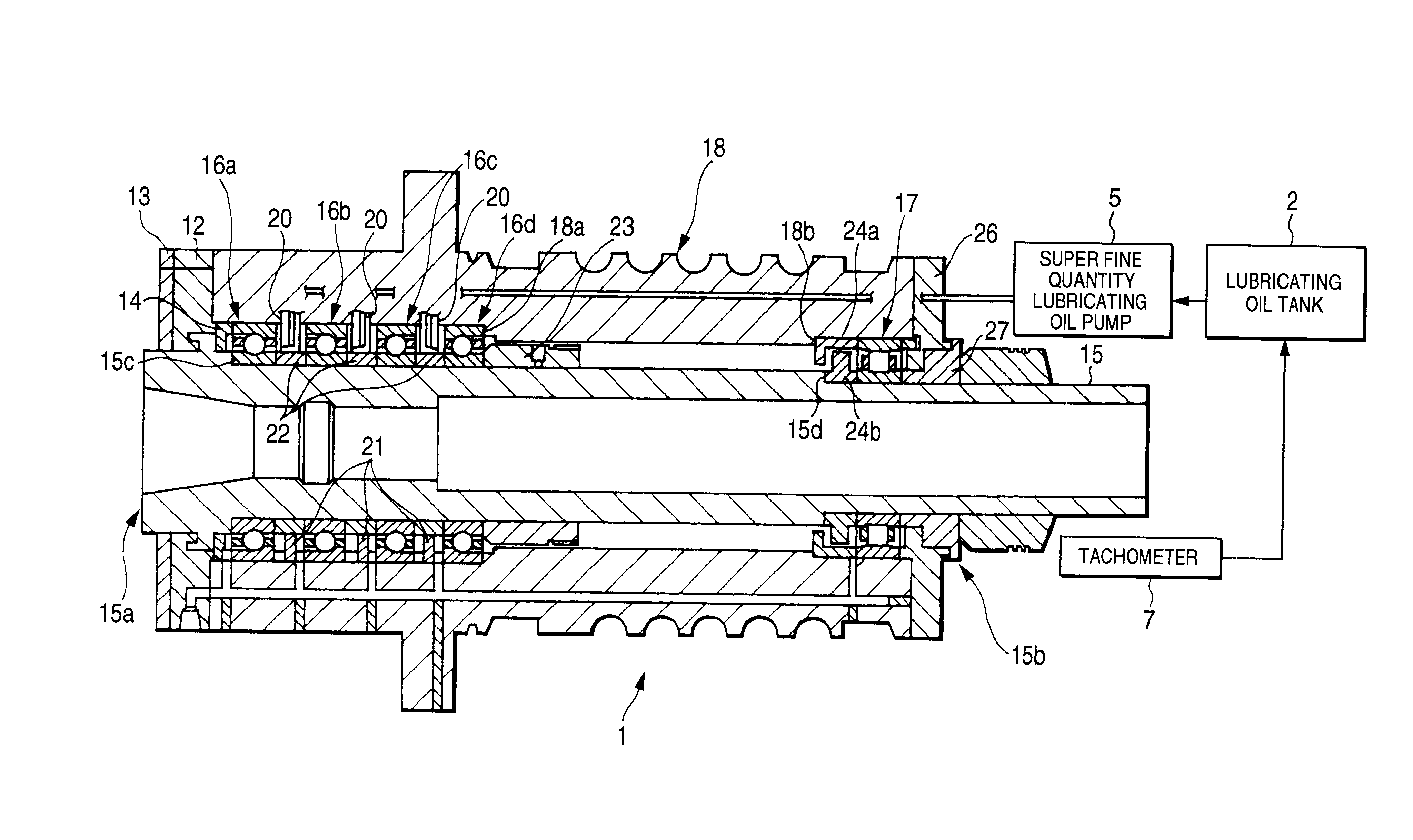
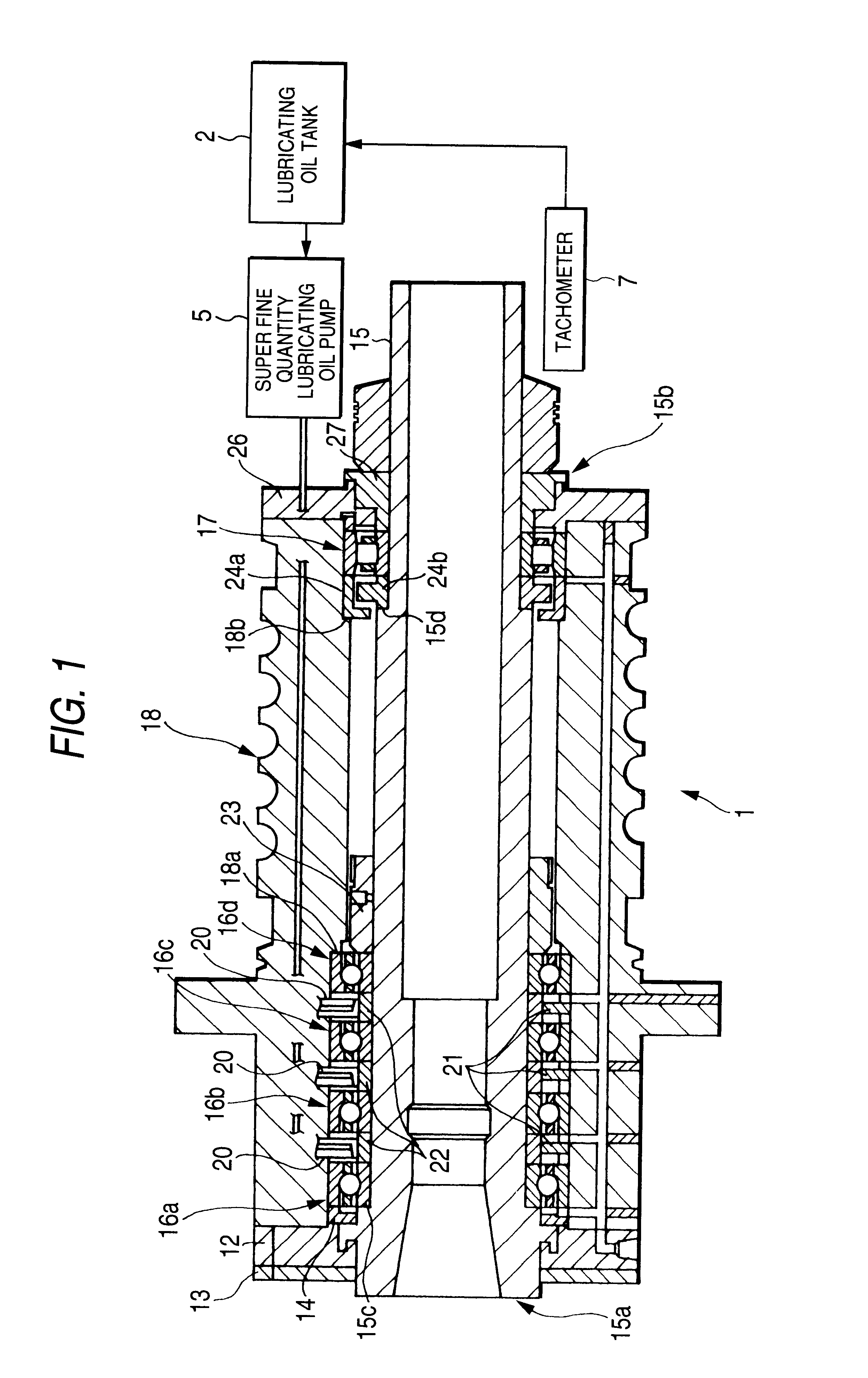
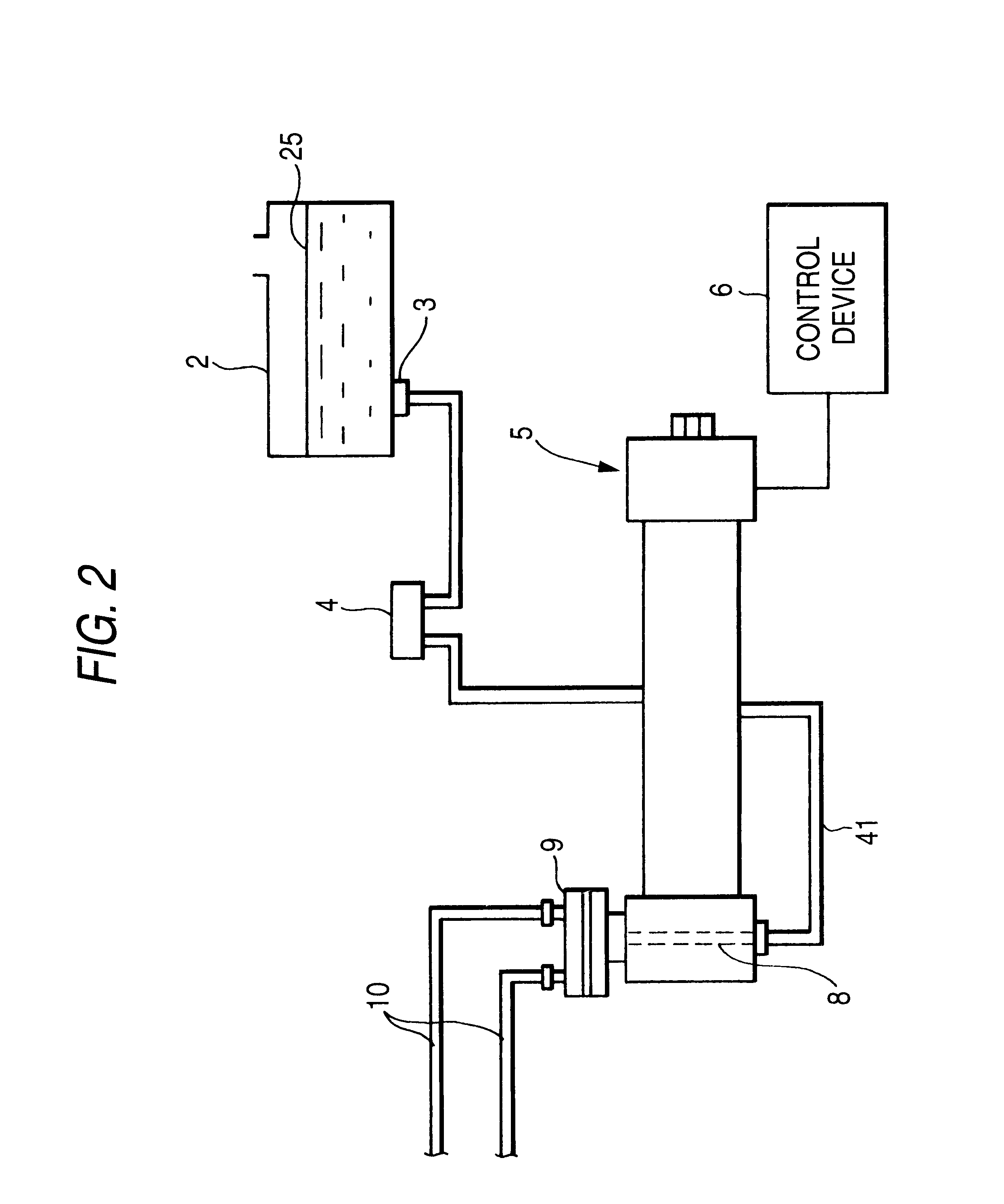
FIGS. 1 and 2 show the structure of a spindle apparatus according to a first embodiment of the invention. The spindle apparatus 1 comprises bearings for spindle 16a, 16b, 16c, 16d and 17 respectively shown in FIG. 1 as well as a lubricating oil tank 2, a lubricating oil filter 3, an air bleed device 4, a super fine quantity lubricating oil pump 5, a control device 6 for controlling the super fine quantity lubricating oil pump 5, a clogging sensor (a pressure sensor) 8, a multi-branch piping device 9, and a pipe 10, respectively shown in FIG. 2 and a tachometer 7 (see FIG. 1).

FIG. 1 is a longitudinal section view of the internal structure of the spindle apparatus 1. As shown in FIG. 1, the spindle apparatus 1 comprises a plurality of angular ball bearings 16a, 16b, 16c and 16d respectively used to support the front portion 15a of a spindle 15 horizontally in a freely rotatable manner, a cylindrical roller bearing 17 for supporting the rear portion 15b of the spindle 15, and a housing...

second embodiment

Next, description will be given below of a second embodiment of a spindle apparatus including a super fine quantity lubricating oil pump composed of an electromagnet and a belleville spring according to the invention. By the way, a structure employed in the present embodiment is similar to that of the spindle apparatus according to the first embodiment except for a lubricating device, and thus the duplicate description thereof is omitted here.

In the case of a super fine quantity lubricating oil pump according to the first embodiment, as a drive source for driving a piston which is used to increase the pressure within a pressurizing chamber (pump chamber), as shown in FIG. 3, there is used the rod-shaped giant magnetostrictive material. As the material of this rod-shaped body, piezo-electric element can also be used depending on the lubricating conditions. A magnetic field or a voltage is applied to the giant magnetostrictive material or piezo-electric element which is connected to t...

third embodiment

Now, description will be given below in detail of a third embodiment of a spindle lubricating apparatus with reference to the accompanying drawings.

Here, FIG. 32 is a schematic view of a spindle lubricating apparatus according to a third embodiment of the invention, and FIG. 33 is a specific structure of a spindle apparatus shown in FIG. 32.

A spindle lubricating apparatus 300 according to the present embodiment includes a spindle apparatus 314, a superfine quantity oil lubricating apparatus with a multi-distribution mechanism 322 and a controller 324. The spindle apparatus 314 includes a plurality of bearings 310a, 310b, 310c, 310d for rotationally supporting a shaft 305 and a plurality of nozzles 312a, 312b, 312c, 312d respectively for discharging lubricating oil to their associated bearings 310a, 310b, 310c, 310d. The superfine quantity oil lubricating apparatus with a multi-distribution mechanism 322 includes a multi-distribution mechanism 320 for distributing lubricating oil, wh...


PUM

PropertyMeasurementUnit
discharge speedaaaaaaaaaa
opening timeaaaaaaaaaa
pitch circle diameteraaaaaaaaaa

Abstract

A rod body (30) is formed of magnetostrictive material and includes one end portion (30a) fixed, and a piston (35) is fixed to the other end portion (35b) of the rod body (30). The piston (35) is slidably disposed within a cylinder (36) in which there is formed a pump chamber (37). A suction port (39) for sucking lubricating oil into the pump chamber (37) is formed in the cylinder (36), while a suction valve (40) for preventing the lubricating oil from flowing out from the suction port (39) is disposed in the suction port (39). In the cylinder (36), there is disposed a nozzle (20) which communicates with the pump chamber (37) and has a sectional area smaller than the lubricating oil passage sectional area of the suction valve (40). There is disposed a coil (43) outside the rod body (30) and, to the coil (43), there is connected a control device (6) for controlling the supply of a current to be supplied to the coil (43).

Description

The present intention relates to a lubricating device which discharges lubricating oil to a spindle apparatus provided in various high-speed rotary machines such as a machine tool and, especially, to the bearing of the spindle.DESCRIPTION OF THE RELATED ARTConventionally, in lubricating the bearing of a high-speed rotary spindle, normally, there are used lubricating devices of various types such as an oil mist type, an oil-air type, and a jet type.The lubricating device of an oil mist type comprises an oil tank, a pump, a plunger, a pressure divider, compressed air, an electromagnetic valve, and a nozzle; and, in this device, lubricating oil is turned into a fine mist-like form, it is delivered through an air pipe using the compressed air, and it is jetted out to the interior portion of the bearing.The lubricating device of an oil-air type comprises an oil tank, a pump, a distributor, a compressed air source, a plunger, and a nozzle; and, in this device, lubricating oil drops (0.01-...

Claims


Application Information

Patent Timeline
Patent Type & Authority Patents(United States)
IPC IPC(8): B23Q1/70B23Q11/12B23Q1/00F04B53/18F04B53/00F04B17/03F04B17/04F16N7/38F16N7/00F16N27/00F01M1/00F16C33/66
CPCB23Q1/70B23Q11/123F04B17/03F04B17/042F04B53/18F16C33/6659F16C33/6674F16N7/38F16N7/385B23Q11/122Y10T409/307224F16N27/00F16C2240/02Y10T409/309352Y10T409/303976F16C2322/39
Inventor NAWAMOTO, TAIKOUSUGIYAMA, KENICHIDAIROKUNO, SATOSHIOKAZAKI, YUKIYOSHI
Owner NSK LTD
Why Eureka
Try Eureka