

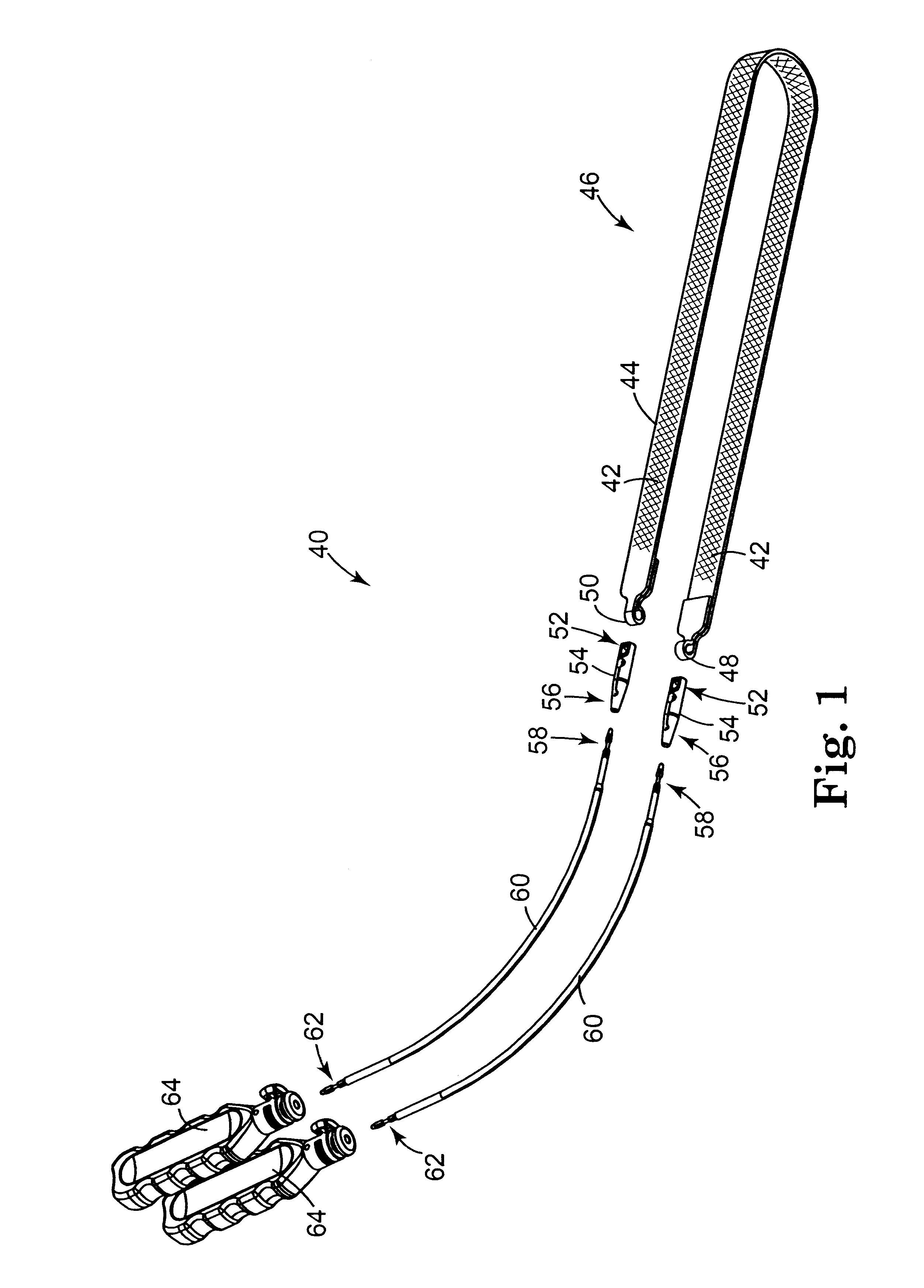
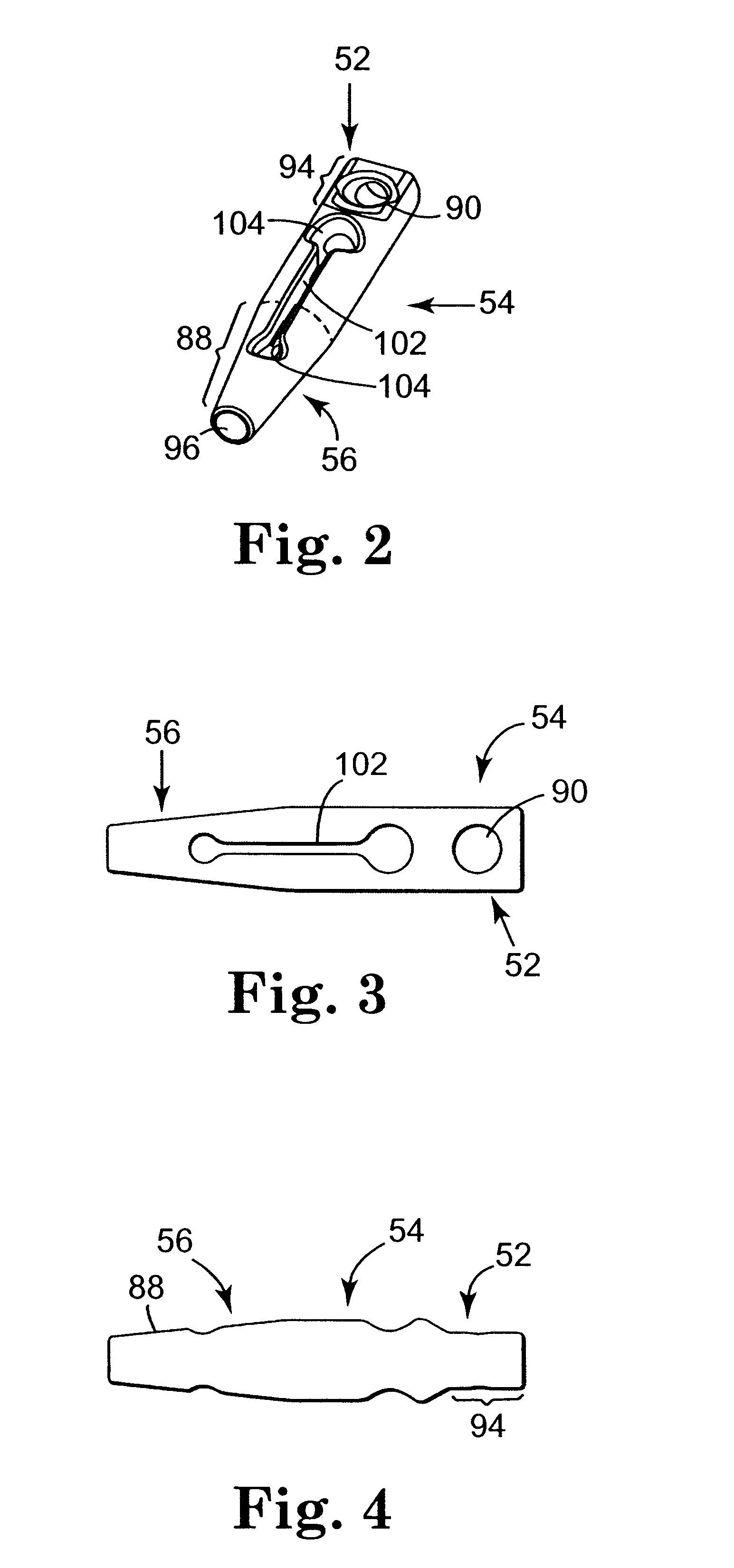
Sling assembly with secure and convenient attachment
a secure and convenient technology, applied in the field of sling assembly and incontinence surgical procedures, can solve the problems of inconvenient or awkward new instrumentation, slow adoption of promising surgical techniques by surgeons, and inconvenient needle connection, so as to facilitate convenient needle connection, reduce rigidity or resistance of radially outward expansion, and reduce the amount of force
- Summary
- Abstract
- Description
- Claims
- Application Information
AI Technical Summary
Benefits of technology
Problems solved by technology
Method used
Image

Examples
example 2
Insertion / Separation Force
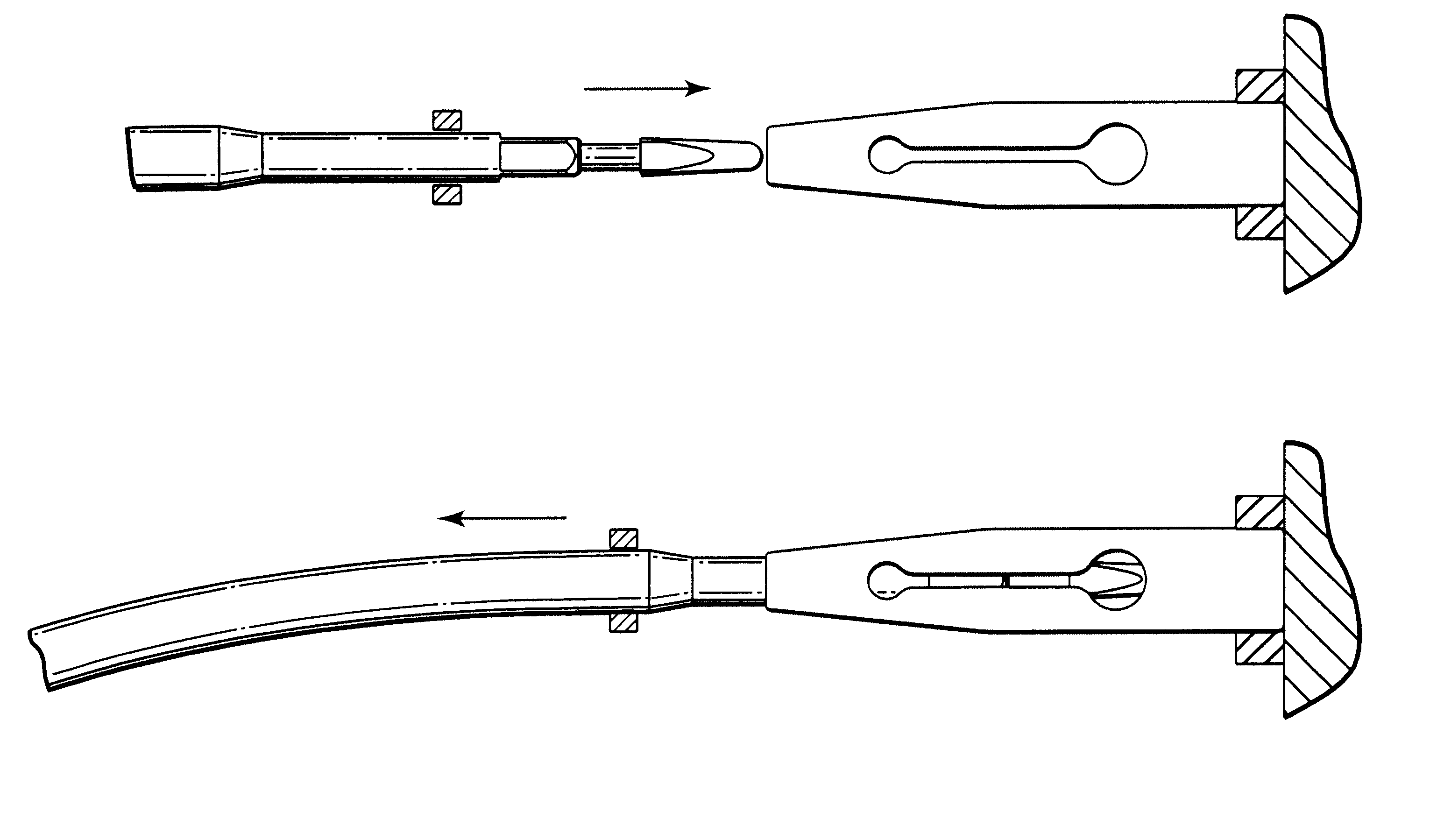
FIGS. 10 and 11 are schematic illustrations of test equipment used to record Separation Forces and Insertion Forces for a needle and couplers. Ten sterilized and aged couplers were provided in accordance with Example 1. A new coupler was used for each Insertion Force / Separation Force test. A single needle was constructed in accordance with Example 1. The needle was used for each Insertion Force / Separation Force test.
The test equipment included an Instron, 200 lb Load cell, Torque Meter device. To obtain the Insertion Force, the needle was loaded into the load cell in the Instron device. The coupler was loaded into a holding fixture (see FIG. 11). The fixture was clamped into the lower air grip of the Instron device. The needle was lowered down and inserted into the coupler to align the needle and coupler but not to induce a load. The needle was then inserted substantially in the direction of the arrow in FIG. 11 at a rate of 0.5 in / sec into the coupler unti...
PUM
 Abstract
Description
Claims
Application Information