
System for protecting electronic test equipment from charged capacitors

a technology for electronic test equipment and capacitors, applied in capacitor testing, emergency protective arrangements for limiting excess voltage/current, instruments, etc., can solve problems such as problems such as the test of capacitors, the damage of other components or the capacitor itself, and the difficulty of testing capacitors

Inactive Publication Date: 2004-01-13
BACHMAN JOHN G
View PDF6 Cites 6 Cited by
  • Summary
  • Abstract
  • Description
  • Claims
  • Application Information

AI Technical Summary

Benefits of technology

In an embodiment of the present invention, a system is provided for permitting electronic measurement equipment to accurately measure the alternating current and pulse characteristics of capacitors regardless of pre-existing charges on the capacitor under test.
In one embodiment, the measuring instrument is connected to the primary coil of a transformer having winding ratios of 1:1:1. The secondary windings of the transformer are connected to each other in opposing polarity through two diodes connected "back to back", and the capacitor under test is connected across the secondary windings. Since the measuring instrument produces low level alternating current signals, the diodes are not conducting, so that the instrument is simply coupled to the capacitor under test through the transformer. This permits normal operation of the instrument.
Another embodiment adds a separate discharging circuit to minimize the amount of discharging current that flows through the transformer windings. A low value blocking capacitor in series with the transformer secondary windings minimizes the current flow while a shunt resistor discharges the capacitor under test.
A further embodiment adds a pair of "back to back" diodes to the discharge shunt resistor. The purpose of these diodes is to decouple the measuring signal from the shunt resistor. Many ESR meters use low level signals to perform the measurement function, but are also able to measure high values of ESR. In such cases, the presence of the discharging shunt resistor could create a measurement error, and adding the decoupling diodes eliminates such error.

Problems solved by technology

However the testing of capacitors is problematic as compared to the testing of resistors.
When testing capacitors, if the capacitor being measured is holding an electrical charge, the measuring instrument, other components or the capacitor itself may be damaged.
In addition, there is the increased safety risk to personnel whenever dealing with charged capacitors that are not properly handled.
The discharging process can be time-consuming, hazardous to personnel, equipment and the meter and equipment.
If personnel skip the discharge process or fail to complete the full discharge process, the capacitor can retain an electrical charge that can damage the measuring instrument and the capacitor itself when testing.
Such arrangements are limited to the current carrying capacity of the relay contacts and the safe discharge current capability of the capacitor under test.
The additional components add to the cost and size of the equipment.
Testing of capacitors that exceed the discharge path limits the effectiveness of the tester.
Finally, employing such a discharge process adds to the time required to perform the testing.
However, the '424 method does not provide full protection from damage, since a large test capacitor with a large charge can still damage meters and equipment.
In U.S. Pat. No. 6,198,290 a method to detect defective capacitors is disclosed, wherein there is a method for measuring the value of capacitors in-circuit, but there is no protection against charged capacitors.
The disclosed design offers little protection, and the device can be damaged by charged capacitors.

Method used


Image

  • System for protecting electronic test equipment from charged capacitors
  • System for protecting electronic test equipment from charged capacitors
  • System for protecting electronic test equipment from charged capacitors

Examples


Embodiment Construction

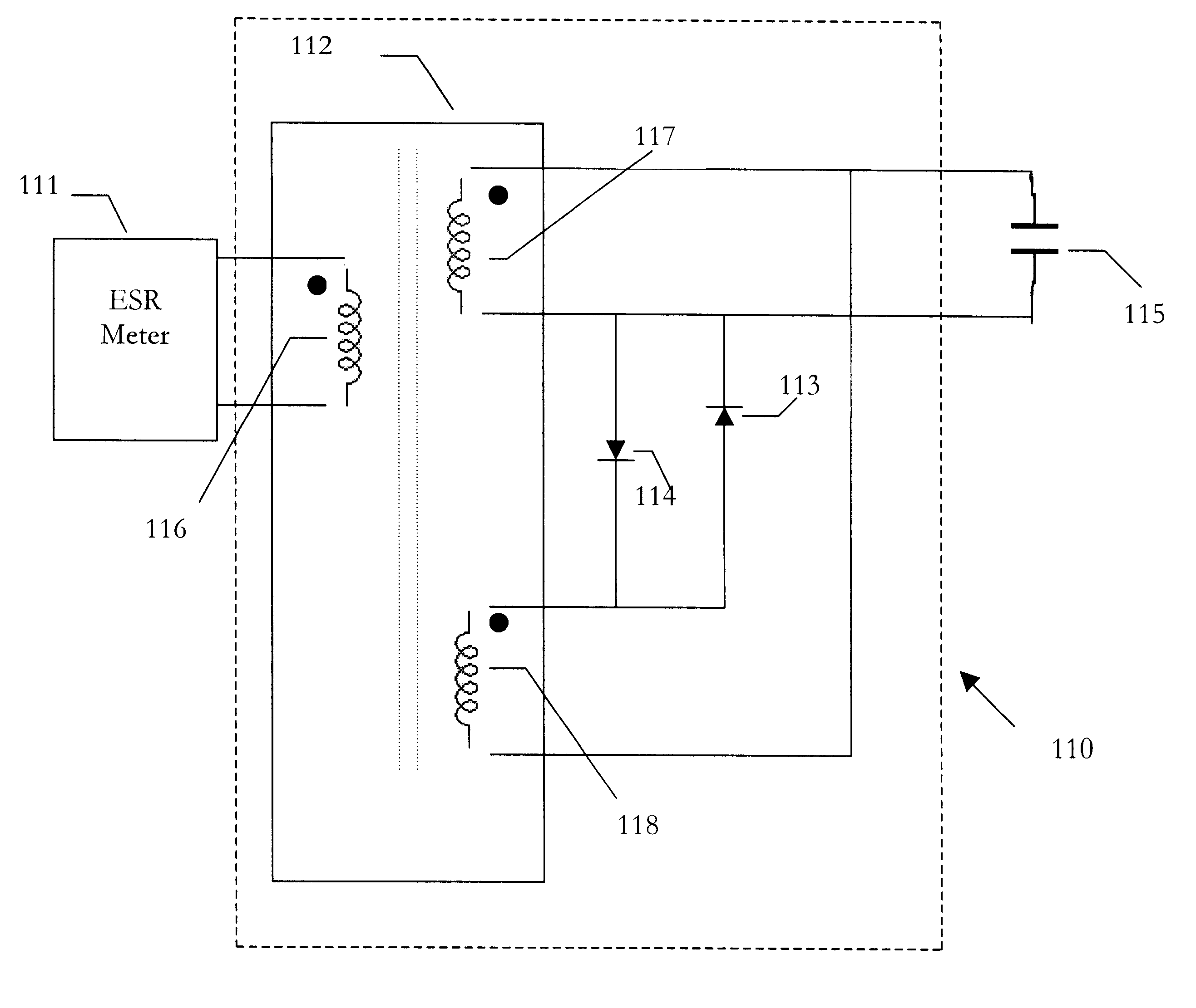
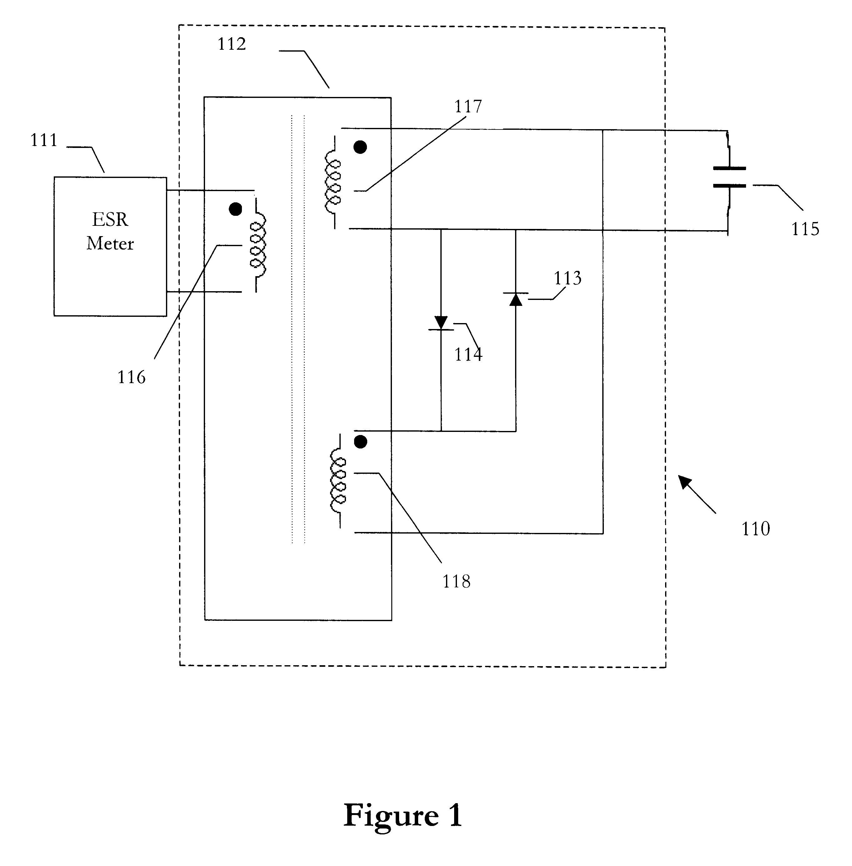
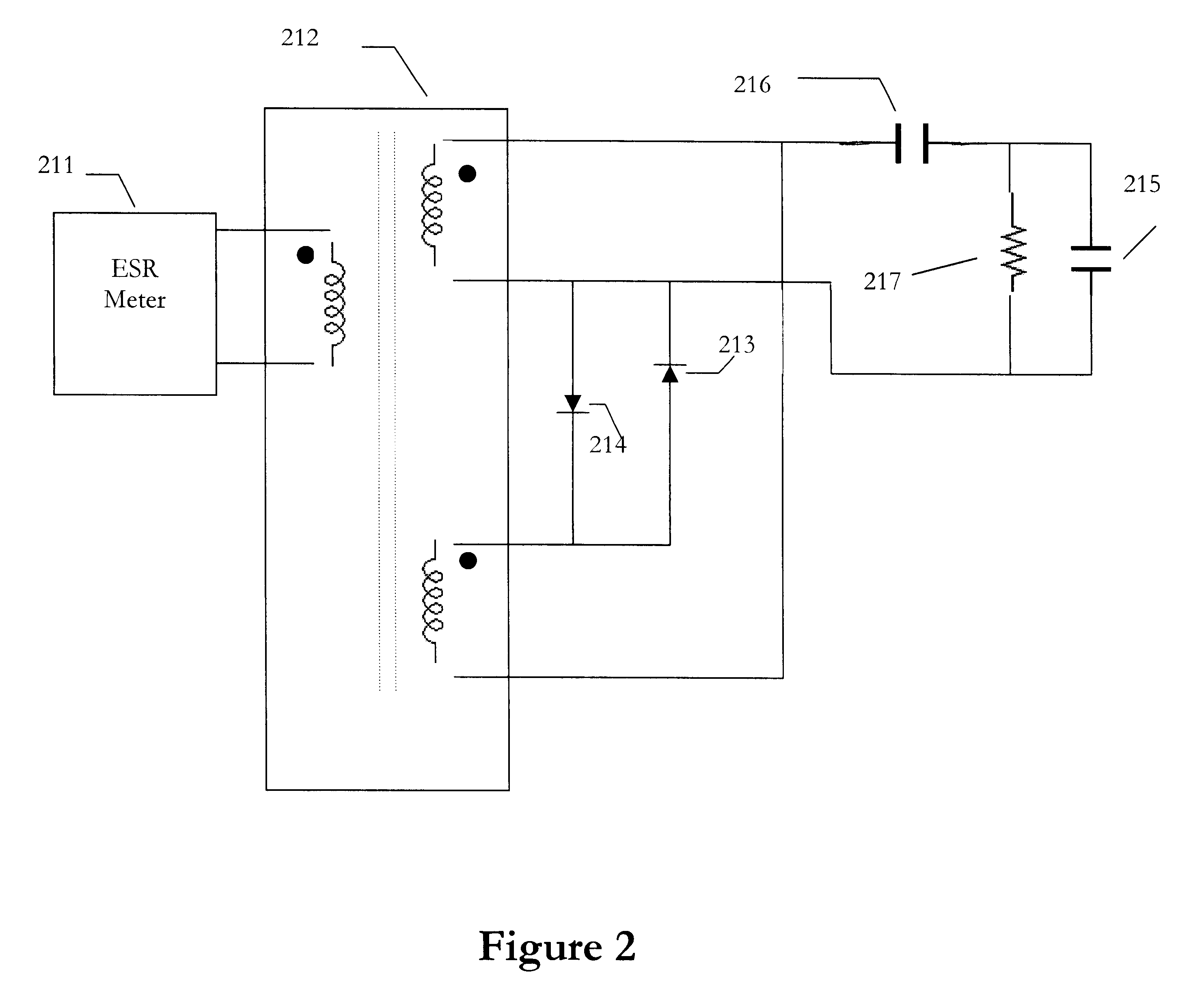
Referring to FIG. 2, there is shown a schematic circuit diagram of an instrument that is connected between an ESR meter 211 and a capacitor being tested 215. The low-level current pulses or ac signals generated by the ESR meter 211 are passed through transformer 212 and blocking capacitor 216 to the capacitor being tested 215.

Since these test signals are low-level, diodes 213 and 214 are not conducting. If the capacitor being tested 215 is holding a charge, then part of that charge is transferred to blocking capacitor 216. This discharge of the capacitor results in a current that causes one of the diodes 213 or 214 to conduct for a period of time determined by the value of the blocking capacitor, the dc resistance of the transformer windings, the leakage inductance of transformer windings and other circuit values. Which diode conducts depends upon the polarity of the charge on the capacitor being tested 215. The secondary windings of transformer 212 are thus connected to each other ...


PUM


Abstract

A system for protecting test equipment intended to perform in-circuit or other low level testing and may connect to a charged capacitor. In one embodimnet, a transformer with three windings is used to couple the ESR meter to the capacitor being tested in a manner that protects the ESR meter. In operation, the ESR meter is connected to the primary winding and the capacitor to be measured is connected to one of the secondary windings. The other secondary winding is connected to the first secondary winding through two diodes that are not conducting during the measurement but do conduct if the capacitor being measured has an electrical charge. The transformer secondary windings are connected to each other so the capacitor discharging currents create flux in the transformer core that are of the same magnitude and opposite polarity, thereby canceling their effect on the primary winding.

Description

1. Technical Field of the InventionThe present invention is in the field of automatic protective devices and pertains in particular to protection of electronic test equipment that performs low level measurement of the characteristics of electronic capacitors.2. Background ArtIn many areas of electronics it is necessary to measure the characteristics of passive electronic components. The ability to accurately pinpoint faulty or defective components has enormous economic value both for production line assembly and repair. Test equipment for measuring and testing of capacitors includes impedance measuring instruments, equivalent series resistance (ESR) meters, and capacitance meters.However the testing of capacitors is problematic as compared to the testing of resistors. When testing capacitors, if the capacitor being measured is holding an electrical charge, the measuring instrument, other components or the capacitor itself may be damaged. In addition, there is the increased safety ri...

Claims


Application Information

Patent Timeline
Patent Type & Authority Patents(United States)
IPC IPC(8): G01R27/26
CPCG01R27/2605G01R31/028G01R31/64
Inventor BACHMAN, JOHN G.
Owner BACHMAN JOHN G
Learn More