Maskless laser beam patterning ablation of multilayered structures with continuous monitoring of ablation

a laser beam patterning and laser machine technology, applied in the field of maskless laser beam patterning ablation with continuous monitoring of ablation, can solve the problems of limited ablation process selectivity, time-consuming and costly creation of physical masks, and patents that do not disclose the desirable ablation etching of low uv absorption

Inactive Publication Date: 2004-02-24
WESTAR PHOTONICS
View PDF12 Cites 181 Cited by
  • Summary
  • Abstract
  • Description
  • Claims
  • Application Information

AI Technical Summary

Problems solved by technology

The above patents do not disclose the desirable ablation etching of low UV absorptive dielectric materials used in the manufacture of semiconductor devices, e.g. silicon dioxide and silicon nitride, which may also be used in combination with polyimides.
Ablation of low absorptive dielectric materials requires radiant energies approaching those needed to ablate metals, which in turn limits ablation process selectivity.
A limitation of the prior art inventions described above is the use of an electrically conductive metallic underlying layer and the use of physical masks to define ablation etch patterns.
Further, the creation of physical masks is time consuming and costly.

Method used


Image

  • Maskless laser beam patterning ablation of multilayered structures with continuous monitoring of ablation
  • Maskless laser beam patterning ablation of multilayered structures with continuous monitoring of ablation
  • Maskless laser beam patterning ablation of multilayered structures with continuous monitoring of ablation

Examples


Embodiment Construction

During the course of this description like numbers will be used to identify like elements according to the different views that illustrate the invention.

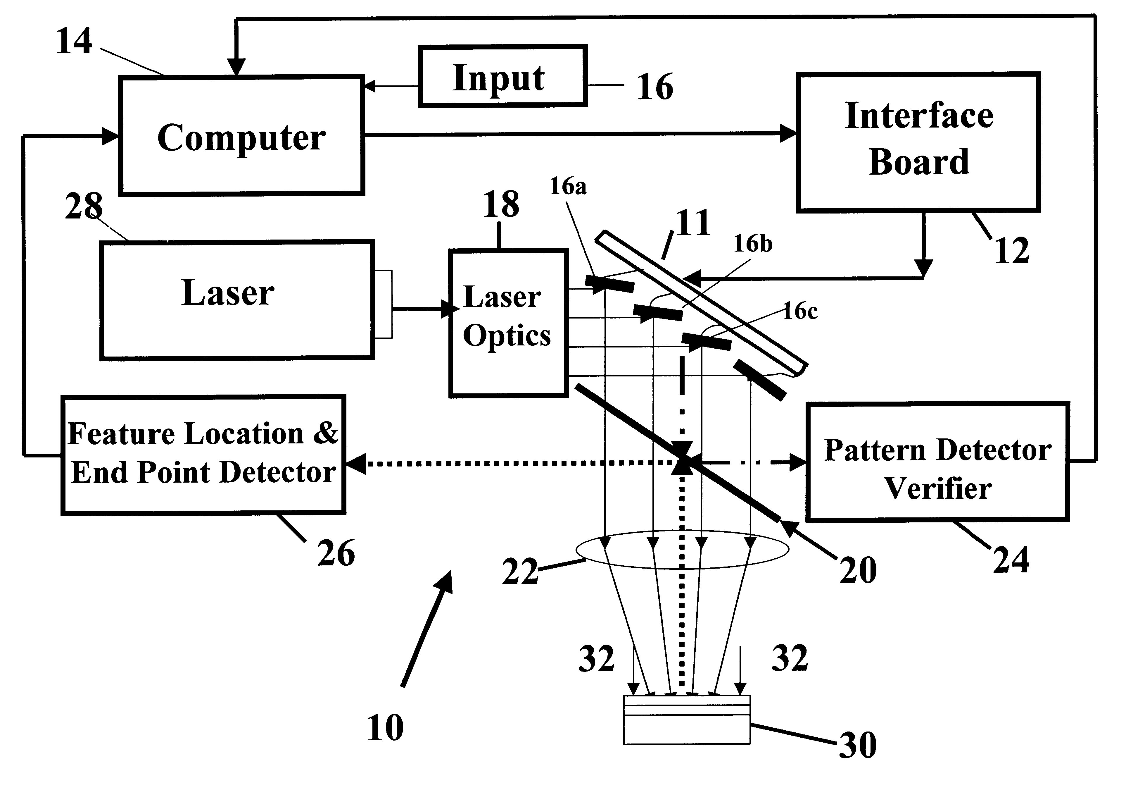
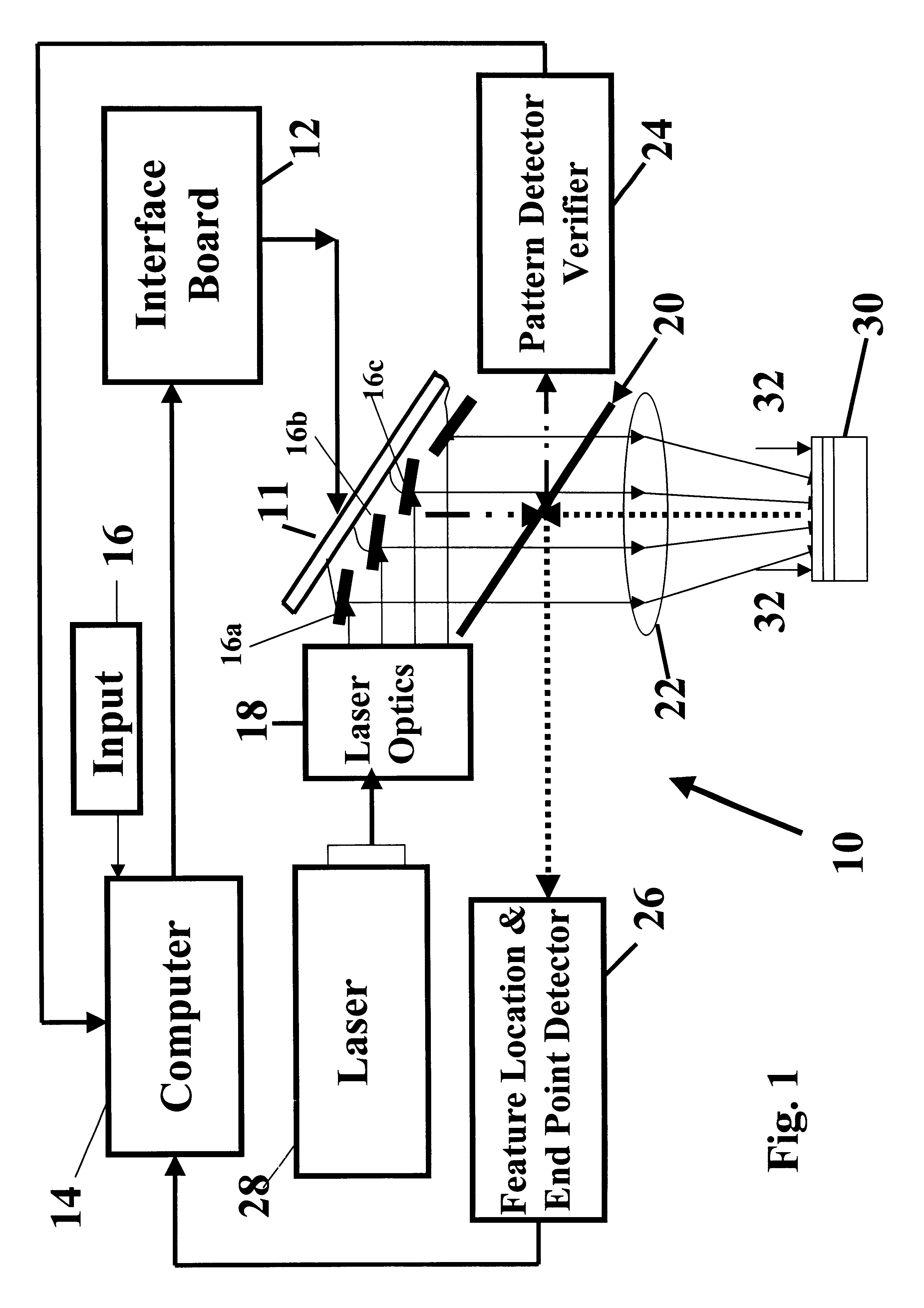
FIG. 1 shows a schematic diagram of a preferred embodiment 10 of the maskless laser beam apparatus of the present invention. The apparatus includes a thin-film micromirror array 11, an interface board 12, a computer 14, a computer input 16, laser optics 18, beam splitter 20, re-imaging optics 22, pattern detector and verifier 24, feature location & end point detector 26, and a laser 28. Operationally, a laser beam emanating from laser 28 is split into a plurality of laser beamlets by laser optics 18, and then modulated and reflected by individual micromirrors 11a,b,c . . . through re-imaging optics 20 onto the surface of workpiece 30.

A key element of this apparatus is the thin-film micromirror 11, which has a plurality of individual micromirrors 11a,b,c . . . , each of which can be individually tilted with respect to incident laser ...


PUM

PropertyMeasurementUnit
widthaaaaaaaaaa
sizeaaaaaaaaaa
sizeaaaaaaaaaa

Abstract

A maskless patterning apparatus allows for laser beam ablation of one or more layers of material while not etching an underlying different material layer. A micromirror array produces the desired complex pattern on the workpiece and a continuous feature and end point detection system provides location and material parameter changes to accurately control the pattern position and depth of etching. End point detection includes monitoring energy reflected from a specially prepared replica of the material to be ablated, whose thickness and consistency match the active workpiece area. The process terminates when the proper amount of material is removed.

Description

1. Field of the InventionThis invention relates to an apparatus and method for laser machine ablation to produce complex patterns suitable for the rapid and accurate patterning of one or more layers of material while not etching an underlying different material layer.2. Description of Related ArtThe use of ablation patterning of various materials including polymers is well known. U.S. Pat. No. 4,508,749, Brannon et al., for example, discloses the use of ultraviolet radiation for etching through a polyimide layer. This patent is aimed at producing tapered openings through the polyimide layer to expose an underlying metal layer so that an electrical connection can be made to the metal. U.S. Pat. No. 5,236,551, issued for Pan describes the use of ablation etching to pattern a polymetric material layer that is then used as a mask for etching patterns in an underlying metal layer with chemical etchants.Polymeric materials have high absorptivity in the region, UV and limited thermal diffu...

Claims


Application Information

Patent Timeline
Patent Type & Authority Patents(United States)
IPC IPC(8): B23K26/02B23K26/073B23K26/03B23K26/06G03F7/20G03F9/00
CPCB23K26/032B23K26/073G03F7/70291G03F7/70558G03F9/70G03F7/2057
Inventor BRANDINGER, JAY J.
Owner WESTAR PHOTONICS
Why Eureka
Try Eureka