Electrochemical etching cell

a technology of electrochemical etching and etching body, which is applied in the direction of cell components, electrolysis components, manufacturing tools, etc., can solve the problems of affecting the electrical or catalytic properties of the etching wafer or the etching body, affecting the etching process, and being contaminated by the dissolved electrode material

Inactive Publication Date: 2004-04-27
ROBERT BOSCH GMBH
View PDF2 Cites 24 Cited by
  • Summary
  • Abstract
  • Description
  • Claims
  • Application Information

AI Technical Summary

Problems solved by technology

However, in known etching apparatuses, the problem continually occurs that at least the anodically connected electrode is at least slightly corroded and dissolved during operation, so that initially the electrolyte, and via it the wafer to be etched, becomes contaminated by the dissolved electrode material in the course of the etching process.
However, in many cases, such contamination, e.g. by platinum in a s...

Method used


Image

  • Electrochemical etching cell
  • Electrochemical etching cell
  • Electrochemical etching cell

Examples


Embodiment Construction

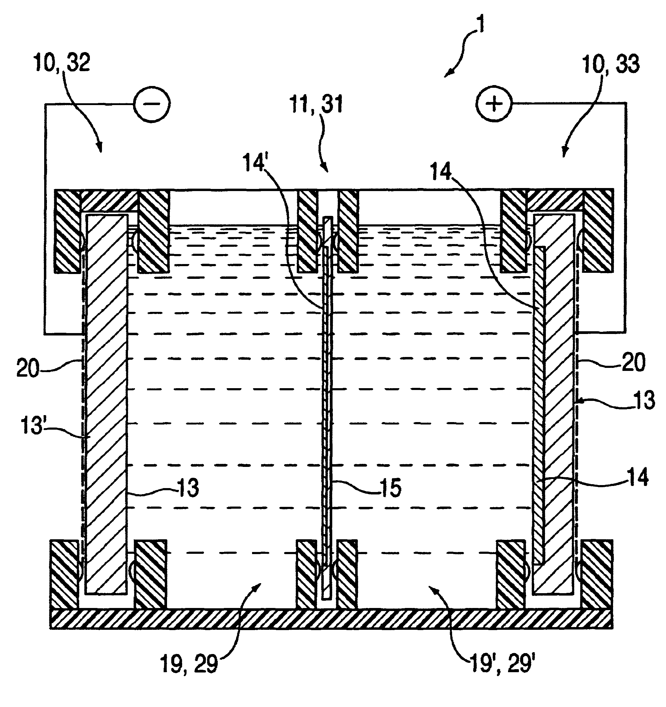
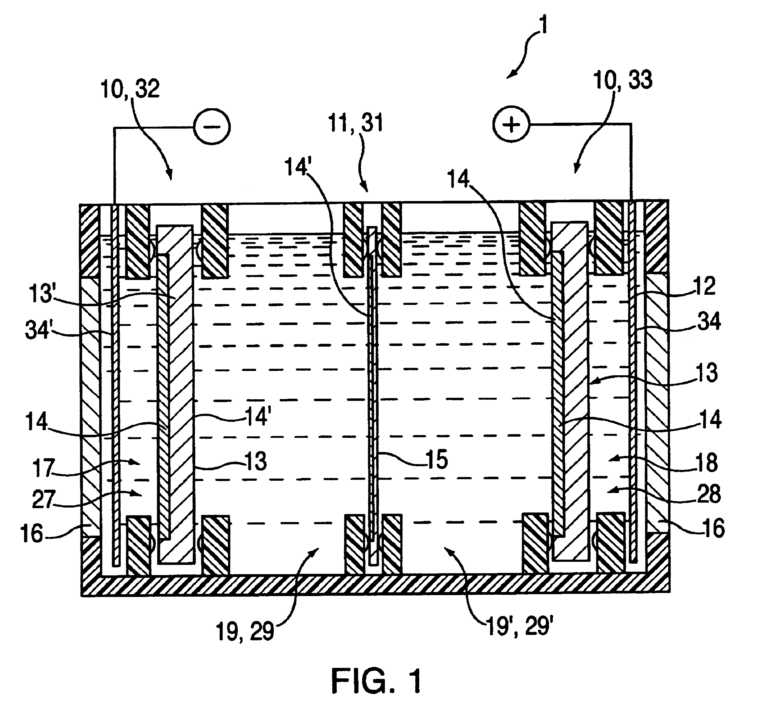
FIG. 1, as a first exemplary embodiment, shows an electrochemical etching cell 1 of the present invention having four chambers, a first chamber 19, a second chamber 19', a third chamber 17 and a fourth chamber 18, each of which is filled at least partially with an electrolyte. First and second chambers 19, 19' are filled, for example, with a mixture of hydrofluoric acid and ethanol for the actual etching of an etching body 15, while third and fourth chambers 17, 18 are filled, for example, with diluted sulfuric acid as contact electrolyte. The four chambers 17, 18, 19, 19' therefore define four electrolyte regions allocated to chambers 17, 18, 19, 19', a first electrolyte region 29, a second electrolyte region 29', a third electrolyte region 27 and a fourth electrolyte region 28 that are separated spatially from one another via separating devices which at the same time, however, permit an electrical connection of chambers 17, 18, 19, 19'.

In detail, first chamber 19 is spatially sepa...


PUM

PropertyMeasurementUnit
Electrical conductoraaaaaaaaaa

Abstract

An electrochemical etching cell (1) is proposed for etching an etching body (15) made at least superficially of an etching material. The etching cell (1) has at least one chamber filled with an electrolyte, and is provided with a first electrode (13), which at least superficially has a first electrode material, and with a second electrode (13') which at least superficially has a second electrode material. Furthermore, the etching body (15) is in contact, at least region-wise, with the electrolyte. In this context, the first electrode material and the second electrode material are selected such that, after the etching, the etching body (15) is not contaminated and/or is not impaired in its properties by the electrode materials. In particular, the electrode materials are the same materials as the etching material. Also proposed is a method for etching an etching body (15) using this etching cell (1), the first and/or the second electrode (13, 13') being used as a sacrificial electrode. The proposed etching cell is particularly suitable for etching silicon wafers in a CMOS-compatible production line.

Description

The present invention relates to an electrochemical etching apparatus, particularly a CMOS-compatible etching apparatus for etching silicon wafers, as well as a method for etching an etching body according to the species defined in the independent claims.BACKGROUND INFORMATIONElectrochemical etching apparatuses, for example, for producing porous silicon or for introducing pores on the surface of silicon, are usually composed of a 2-chamber system, between which a silicon wafer to be etched is clamped as a separating wall, and the two chambers being electrically coupled or connected to one another only by the wafer. Furthermore, electrodes, generally made of platinum, are usually placed in both chambers for the current supply. For example, such an etching apparatus is already described fully and in its essential details by Fujiyama et al in the U.S. Pat. No. 5,458,755.However, in known etching apparatuses, the problem continually occurs that at least the anodically connected electrod...

Claims


Application Information

Patent Timeline
IPC IPC(8): C25F7/00C25F3/12H01L21/3063
CPCC25F7/00Y10S204/12H01L21/3063
Inventor ARTMANN, HANSFREY, WILHELMLAERMER, FRANZ
Owner ROBERT BOSCH GMBH
Why Eureka
Try Eureka