Widely wavelength tunable integrated semiconductor device and method for widely tuning semiconductor devices

a semiconductor device and wavelength tunable technology, applied in the direction of laser cooling arrangement, laser details, electrical equipment, etc., can solve the problems of low selectivity and low tuneability of a conventional distributed bragg reflector (dbr) semiconductor laser, limited tuning of a conventional dbr semiconductor laser, and increase of two reflector sections, etc., to achieve low lasing output power loss, wide range of tuning, and easy manufacturing

Inactive Publication Date: 2004-04-27
INTERUNIVERSITAIR MICRO ELECTRONICS CENT (IMEC VZW) +1
View PDF10 Cites 71 Cited by
  • Summary
  • Abstract
  • Description
  • Claims
  • Application Information

AI Technical Summary

Benefits of technology

The aim of the present invention is to disclose laser structures which are easy to manufacture and which are widely tuneable and have low lasing output power losses.

Problems solved by technology

Tuning of a conventional Distributed Bragg Reflector (DBR) semiconductor laser is limited by the fact that the relative tuning range is restricted to the relative change in the refractive index of the tuning region.
These two parallel waveguides cannot be considered as resonators, indeed the spectra (shown in FIG. 10b and c) show the comb mode spectra corresponding to arms B and A, but they are either the comb mode spectra of arm B, the gain section and the reflectors R or the comb mode spectra of arm A, the gain section and the reflectors R. As the spacing between the spectral lines are determined by the length of the structures, it appears that said spacing is still very small, resulting in still a low selectivity and a low tuneability.
The disadvantage of the (S)SG-DBR approach is that light coupled out of the laser has to pass a long passive or inactive section, leading to loss.
Also, the losses in the two reflector sections increase with the amount of current injected into those sections, leading to a tuning current dependent output power.
As the construction of said reflectors leads to long inactive sections, this results in lasing output power losses.
Other lasers, which use a co-directional coupler, readily have a very wide tuning range, but there is insufficient suppression of neighbouring longitudinal modes.
Unfortunately, such a structure is rather complicated to manufacture, requiring at least 5 growth steps.
The disclosed structure enables generation of multiple wavelengths, even sumultaneously, but does not address the issue of selectivity and tuneability.
The disclosed structure again enables radiation of a plurality of wavelengths but does not address the issue of tuneability.

Method used


Image

  • Widely wavelength tunable integrated semiconductor device and method for widely tuning semiconductor devices
  • Widely wavelength tunable integrated semiconductor device and method for widely tuning semiconductor devices
  • Widely wavelength tunable integrated semiconductor device and method for widely tuning semiconductor devices

Examples


first embodiment

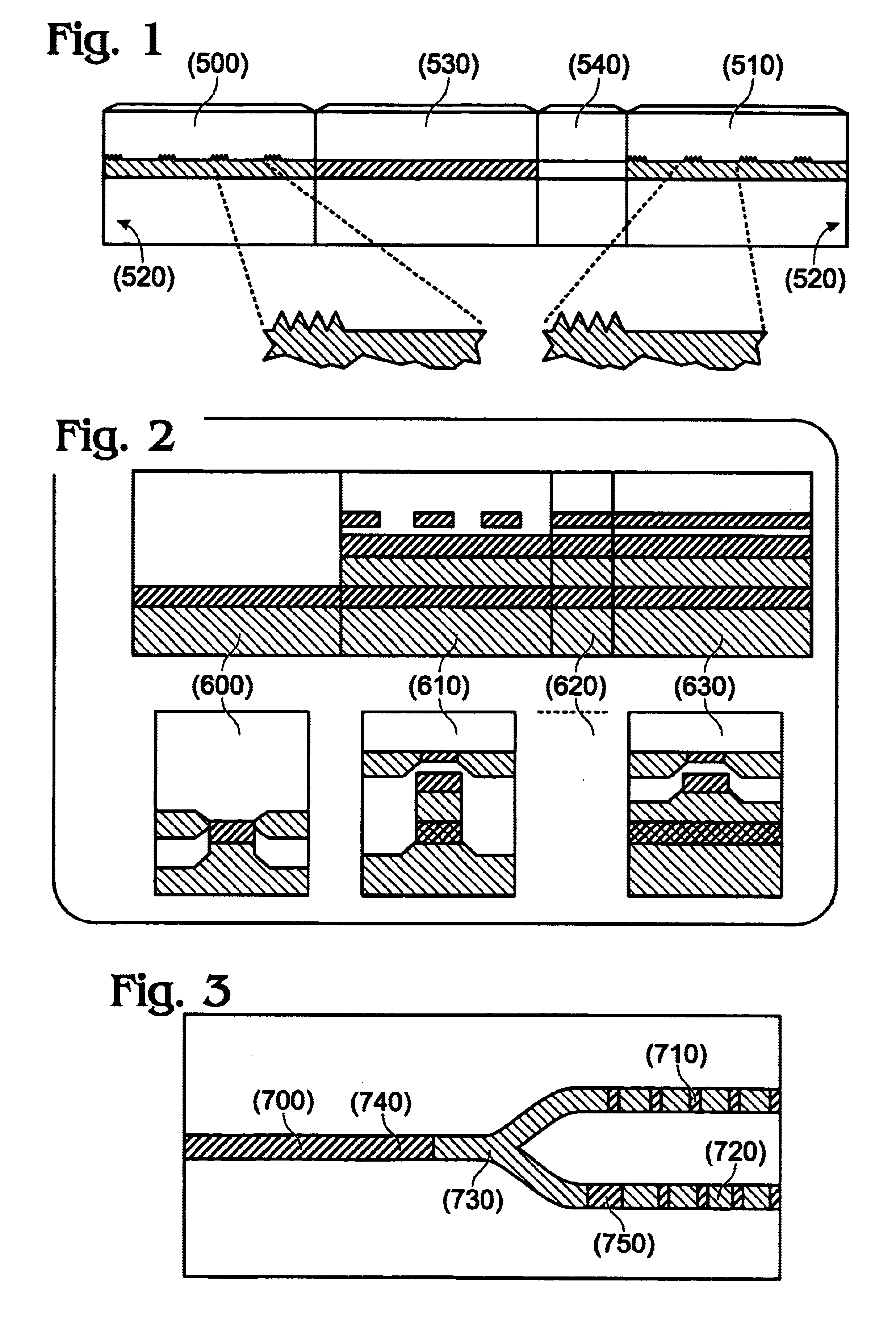
In a first embodiment, a Y-structure as in FIG. 3 is proposed with two reflectors 710, 720, placed on the same side of the active region 700. These two reflectors use sampled or super structure gratings to provide reflection combs with different periods; their design is the same as for (S)SG-DBR lasers. The power splitter 730 is used to split / combine the light leaving / entering the active region 700. Two phase control sections 740, 750 are shown in FIG. 3. One provides the correct phase relation between the signals reflected by the two reflectors, whereas the second provides control of the overall phase of the combined reflected signal. According to an alternative embodiment, a separate phase control section could be placed in each of the arms of the Y. The branches of the Y-structure could be all-active, thus avoiding a (technologically more complex) transition from an active waveguide to a passive one. However, this has the disadvantage that the device will be more difficult to con...

second embodiment

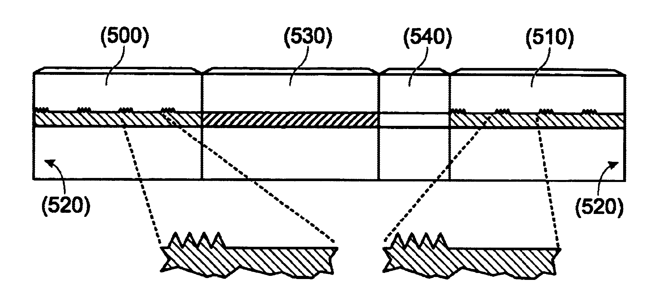
In a second embodiment, a second structure, which in a top view looks like in FIG. 8, is proposed. In this structure, a plurality of reflectors 440 (including reflectors 410, 420, 430) are placed on the same side of the active region 400. At least two of said reflectors use sampled or super structure gratings to provide reflections combs. At least two of said reflectors have reflection combs with different periods. The design of said reflectors is the same as for (S)SG-DBR lasers. The power splitter 450 is used to split and combine the light leaving / entering the active region 400. Phase control sections can be introduced. In one configuration one phase control section is placed between the active region and the reflectors and in all reflectors, except one, also a phase control section is provided. In another configuration only phase control sections are provided in said reflectors.

third embodiment

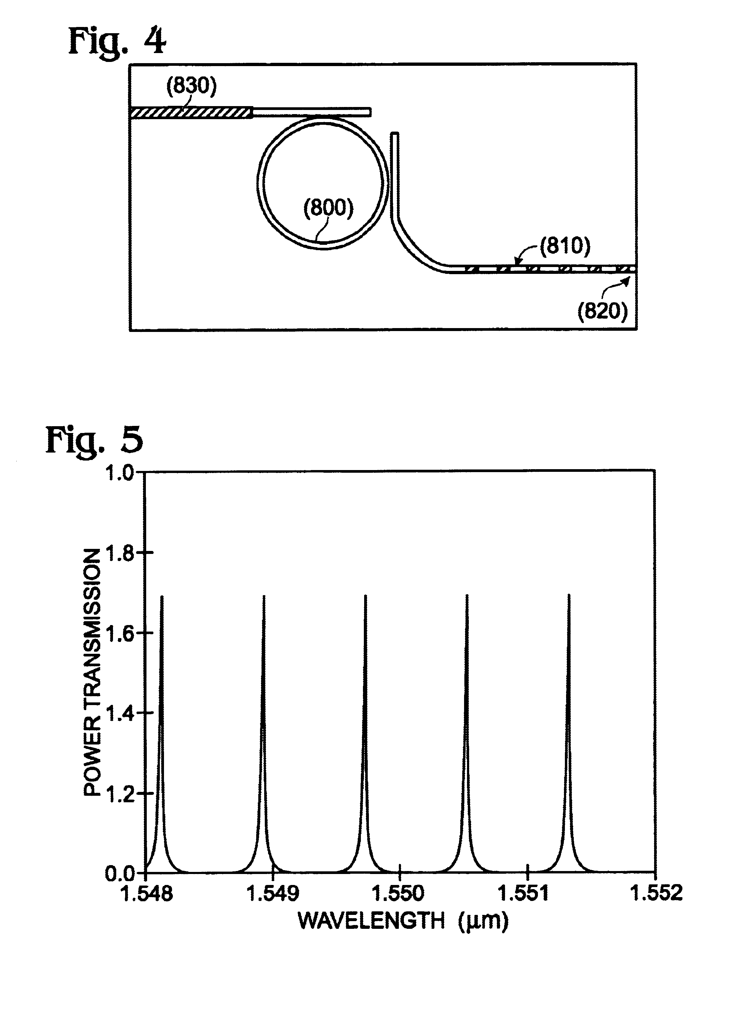
In a third embodiment, a third structure, as shown in FIG. 4, is proposed. The reflector consists of an active section 830, a ring resonator 800, which has a comb-shaped transmission characteristic (one example is shown in FIG. 5) and a (S)SG-reflector 810 with, in one embodiment, anti-reflective coating 820. The operation of a ring resonator is similar to that of a classic Fabry-Perot resonator, which can easily be understood if one thinks of the cross-coupling of the two couplers in the ring as being the transmission mirrors in the FP-resonator. The tuning is again based on the "Vernier"-principle, as in conventional (S)SG-DBR lasers: the ring resonator and the (S)SG-reflector are designed to have slightly different peak-spacing in their transmission and reflection characteristics respectively, and lasing occurs at or near the wavelength where two peaks overlap each other. A phase section, used to align a longitudinal cavity mode with the two aligned peaks, could also be included ...


PUM


Abstract

Alternative laser structures, which have potentially the same tuning performance as (S)SG-DBR and GCSR lasers, and a fabrication process which is similar to that of the (S)SG-DBR laser, are presented. The advantage of these structures is that the output power does not pass through a long passive region.

Description

The invention relates to multi-section integrated semiconducting devices or lasers, comprising resonator sections, being either distributed reflection or transmission sections. The invention also relates to methods for widely wavelength tuning semiconductor devices or lasers.Tuning of a conventional Distributed Bragg Reflector (DBR) semiconductor laser is limited by the fact that the relative tuning range is restricted to the relative change in the refractive index of the tuning region. This means that the tuning range, under normal operating conditions, cannot exceed 10 nm. This is substantially less than the potential bandwidth, restricted by the width of the gain curve, which is about 100 nm. Such conventional DBR lasers can functionally be characterized as comprising a first part being a two-sided active section, for creating radiation, for instance a light beam, by spontaneous emission over a bandwidth around one center frequency. Said first part also guides said radiation or l...

Claims


Application Information

Patent Timeline
Patent Type & Authority Patents(United States)
IPC IPC(8): H01S3/10H01S5/00H01S5/0625H01S5/10H01S5/12
CPCH01S5/06256H01S5/1003H01S5/1071H01S5/1209H01S5/1218
Inventor SARLET, GERTBUUS, JENSBAETS, ROEL
Owner INTERUNIVERSITAIR MICRO ELECTRONICS CENT (IMEC VZW)
Why Eureka
Try Eureka