Ion generating device

a generation device and ion technology, applied in the field of ion generating devices, can solve the problems of inability to ensure inability to ensure the long-term and consistent production of ions, and possible negative ions to circulate,

Inactive Publication Date: 2004-05-18
GENIE & ENVIRONNEMENT
View PDF5 Cites 60 Cited by
  • Summary
  • Abstract
  • Description
  • Claims
  • Application Information

AI Technical Summary

Benefits of technology

FIG. 4 shows the structure of a ...

Problems solved by technology

Firstly, their performance is limited and incapable of ensuring long term and consistent production of ions. In particular they do not make it possible to cause a negative flux of ions to circulate constantly in the site or the enclosure to be treated.
Nor do they make it possible to provide and extend the flux of ions and the diffusion of ions throughout the entire enclosure or premises to be treated, and they are not very reliable concerning actual production of ions.
Known apparatuses also have rather low efficiency in producing ions after they have been in use for a while.
In particular, after they have been used several times, they are found to be poor at producing oxygen ions effectively.
Those that operate at a voltage in excess of 6 kV are dangerous because of the aggressivity and the toxicity of the peroxiding substances they produce, such as ozone and nitrogen oxides.
In addition, the use of voltages that are too high is very difficult to control or master, and is therefore very dangerous for an everyday application.
However, whatever the systems or protective methods in existence heretofore, they do not manage to avoid creating rubbing and air circulation and diffusion inside the housing, thereby building up static charge and/or favoring the formation of peroxide type compounds.
Unfortunately, static charge reduces the yield of the mass of ions created.
Nor do such apparatuses ensure that the emitter needles are consistent and stable, nor do they ensure that the production from each needle is consistent, regular, and controllable in order to produce ion fluxes having a lifetime that is sufficient for enabling an intended or identified premises to be treated normally and durably.
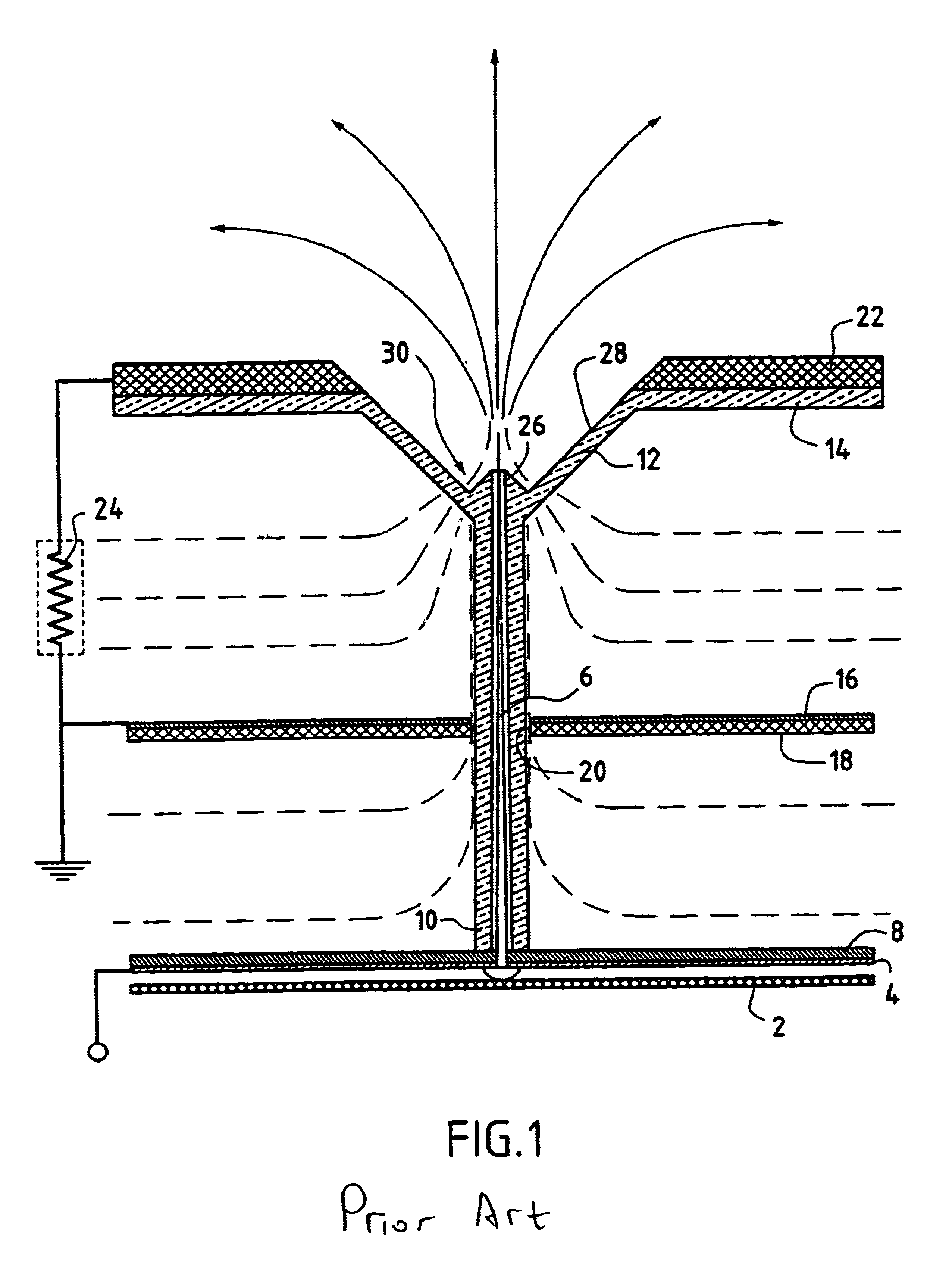
The apparatus described in document WO 96/02966 also requires a conical opening 28 which makes it possible to touch the needles, which is dangerous in some applications, in particular in cars or in day nurseries.
These connections also create a deficiency in the high voltage power supply, and do not prevent losses or static charges.
The apparatuses therefore cannot genuinely ensure high quality production of ions and dispersa...

Method used


Image

  • Ion generating device
  • Ion generating device
  • Ion generating device

Examples


first embodiment

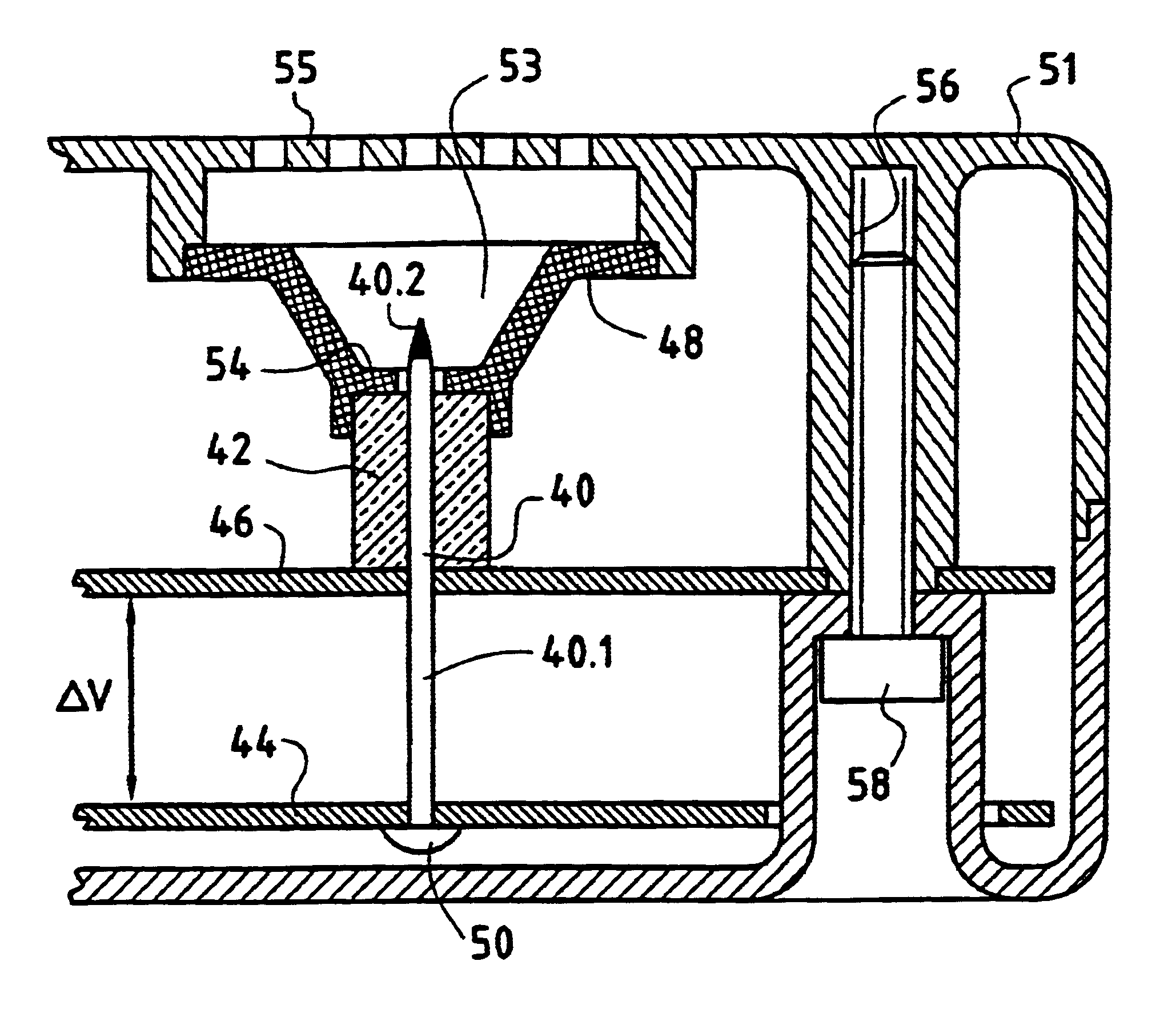
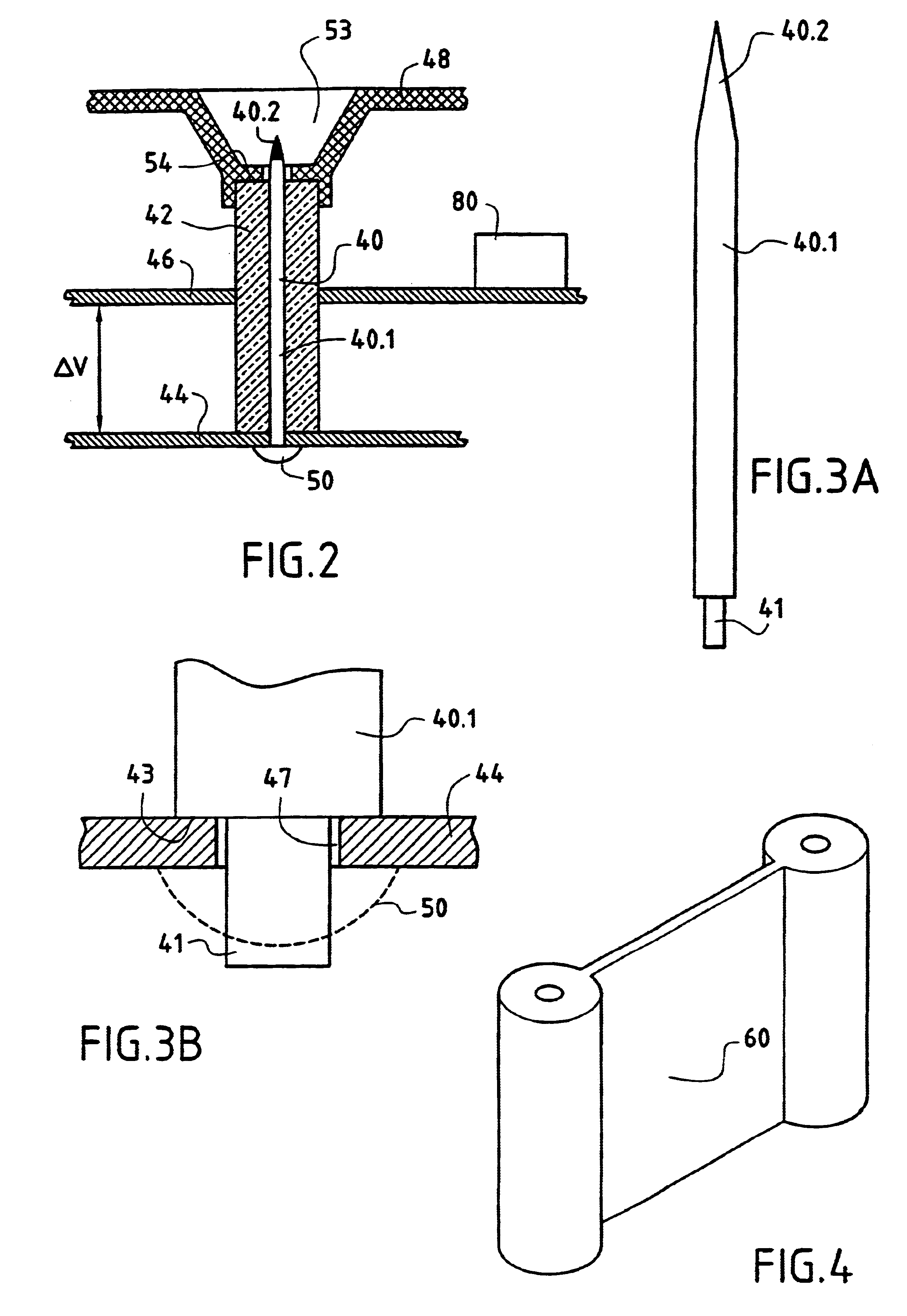
apparatus of the invention is described with reference to FIG. 2.

The apparatus comprises an emitter needle or "point" 40 essentially made of a noble material. The needle is preferably made of titanium or of platinum or of a compound of those two materials.

It is also possible to use a stainless metal or indeed silver, stainless steel, brass, or nickel, or an alloy of those materials, e.g. a brass-nickel alloy or a silver-stainless steel alloy. Nevertheless, it is titanium or platinum or a platinum-titanium mixture that provides best performance for the apparatus, as explained below.

The needle has a cylindrical portion 40.1 extended by a conical end 40.2.

It is inserted in a sheath 42 of a composite material based on glass fiber reinforced unsaturated polyester.

Such a material can also include chlorophthalic resin.

The material can be formed by pultrusion, for example.

By way of example, the material of the sheath 42 can have a glass content lying in the range 50% by 80% by weight of the...

example i

A first example concerns a study on the effectiveness of the ionizer in a gray airlock for loader personnel (in a unit in the pharmaceutical industry).

As described above, the apparatus used is capable of emitting 4.times.10.sup.12 negative ions per second, thus enabling it to process on average 80 m.sup.3 to 100 m.sup.3 of air

The apparatus was placed in the gray airlock for loader personnel. A high level of microbial contamination of the air had been observed in the airlock, over a period of several weeks.

Tests were performed before the ionizer was installed, and while the ionizer was in use.

Particular tests were performed using a METONE 217 type particle counter, serial number 92 22 51 47 MM, fitted with an isokinetic probe. Tests were performed during periods of activity. That applies to particle testing.

In addition, bacteriological tests were performed. Tests were applied to ambient air and to surfaces (wash-basins and floors). Tests were performed in the same manner as routine s...

example ii

This example relates to the effect of an ionizer in a delivery room.

The volume treated was 1200 m.sup.3 and seven apparatuses of the invention were installed in the room.

Tests were performed by a biological hygiene technician when the room was at rest without any human presence, on Apr. 9, 1998 (day D0 prior to equipment being installed) and on April 10 and Apr. 11, 1998 (respectively days D1 and D2).

The particle counting apparatus used was of the "MET ONE 227" type having a flow rate of 2.8 liters per minute, with samples being taken over a duration of 1 minute. That apparatus was installed in the middle of the room.

Measurements of biological contamination of the air were performed using an apparatus of the "SAMPL'AIR" type at a flow rate of 100 liters per minute with samples taken over a period of 10 minutes. That apparatus was likewise installed in the middle of the room.

The results of particle counting and of performing microbiological tests on surfaces, and of testing air for b...


PUM


Abstract

The invention relates to apparatus for generating ions in a gaseous medium, the apparatus comprising one or more needles (40) each presenting a shank (40.1) and an emitter end (40.2), a sheath (42) of composite material comprising glass fiber reinforced unsaturated polyester surrounding the shank (40.1) of each needle, and means (44, 46, 80) for applying a voltage between two portions of the shank of each needle.

Description

TECHNICAL FIELD AND PRIOR ARTThe present invention relates to electronic apparatuses of the "ion generator" type. Such apparatuses enable a certain density of ions (e.g. of negative oxygen ions in air) to be maintained within an enclosure or in premises in order to make the place where ions are being diffused more healthy.An application of the invention relates to maintaining a certain density of ions, e.g. negative oxygen ions in air, inside any closed or semi-open enclosure or premises having a ventilation system in order to restore health to the place where controlled ion diffusion is being applied.Such an ion generator apparatus is known from document WO 96 / 02966.The structure of that known apparatus essentially comprises:a first subassembly constituted by an electron optics system; anda second subassembly constituted by a power supply unit delivering a high voltage of the order of 4 kV to 5 kV between an output S and a common ground M, and at an impedance of about 100 Megohms; ...

Claims


Application Information

Patent Timeline
IPC IPC(8): H01T23/00A01K1/02A23B4/16A23B7/144A23L3/3409A47B71/00B03C3/02B03C3/40B03C3/41B65B31/00F03H1/00H01T19/04
CPCH01T23/00
Inventor MERCIEL, JOEL
Owner GENIE & ENVIRONNEMENT
Why Eureka
Try Eureka