Methods and apparatus for presbyopia treatment using a scanning laser system

a scanning laser and presbyopia technology, applied in the field of presbyopia apparatus and methods, can solve the problems of inability to present any details or practical methods or laser parameters for presbyopia correction, the limitations of the above-described prior arts, and the inability to use them

Inactive Publication Date: 2004-06-08
NEOS OCULAR
View PDF10 Cites 41 Cited by
  • Summary
  • Abstract
  • Description
  • Claims
  • Application Information

AI Technical Summary

Benefits of technology

It is yet another objective of the present invention to use a scanning device such that the degree of ciliary mussel accommodation can be controlled by the location, size and shapes of the removed sclera tissue.
It is yet another embodiment of the present surgical laser to provide an integration system in which the sclera ablation leads to the increase of the accommodation of the ciliary muscle for the treatment of presbyopia and the prevention of open angle glaucoma.

Problems solved by technology

The above-described prior arts are however limited to the use of reshaping the corneal surface curvature for the correction of myopia and hyperopia.
These mechanical approaches have the drawbacks of complexity and are time consuming, costly and have potential side effects.
However, these prior arts do not present any details or practical methods or laser parameters for the presbyopic corrections.
No clinical studies have been practiced to show the effectiveness of the proposed concepts.
The concepts proposed in the Schachar patents regarding lasers suitable for ablating the sclera tissues were incorrect because he did not identify which lasers are "cold lasers".
Furthermore, the clinical issues, such as locations, patterns and depth of the sciera tissue removal were not indicated in these prior patents.
This method, however, involves a lot of bleeding and is difficult to control the depth of the cut which requires extensive surgeon's skill.
Another drawback for presbyopia correction provided by the above-described non-laser methods is the major post-operative regression of about (30%-80%).

Method used


Image

  • Methods and apparatus for presbyopia treatment using a scanning laser system
  • Methods and apparatus for presbyopia treatment using a scanning laser system
  • Methods and apparatus for presbyopia treatment using a scanning laser system

Examples


Embodiment Construction

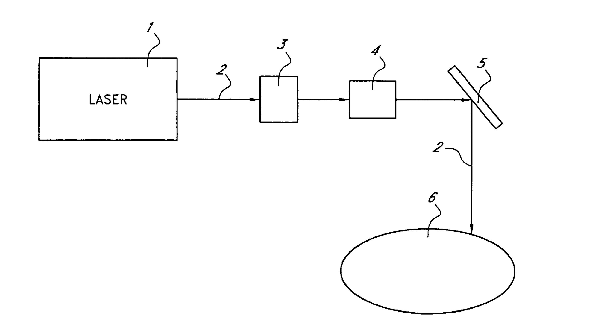
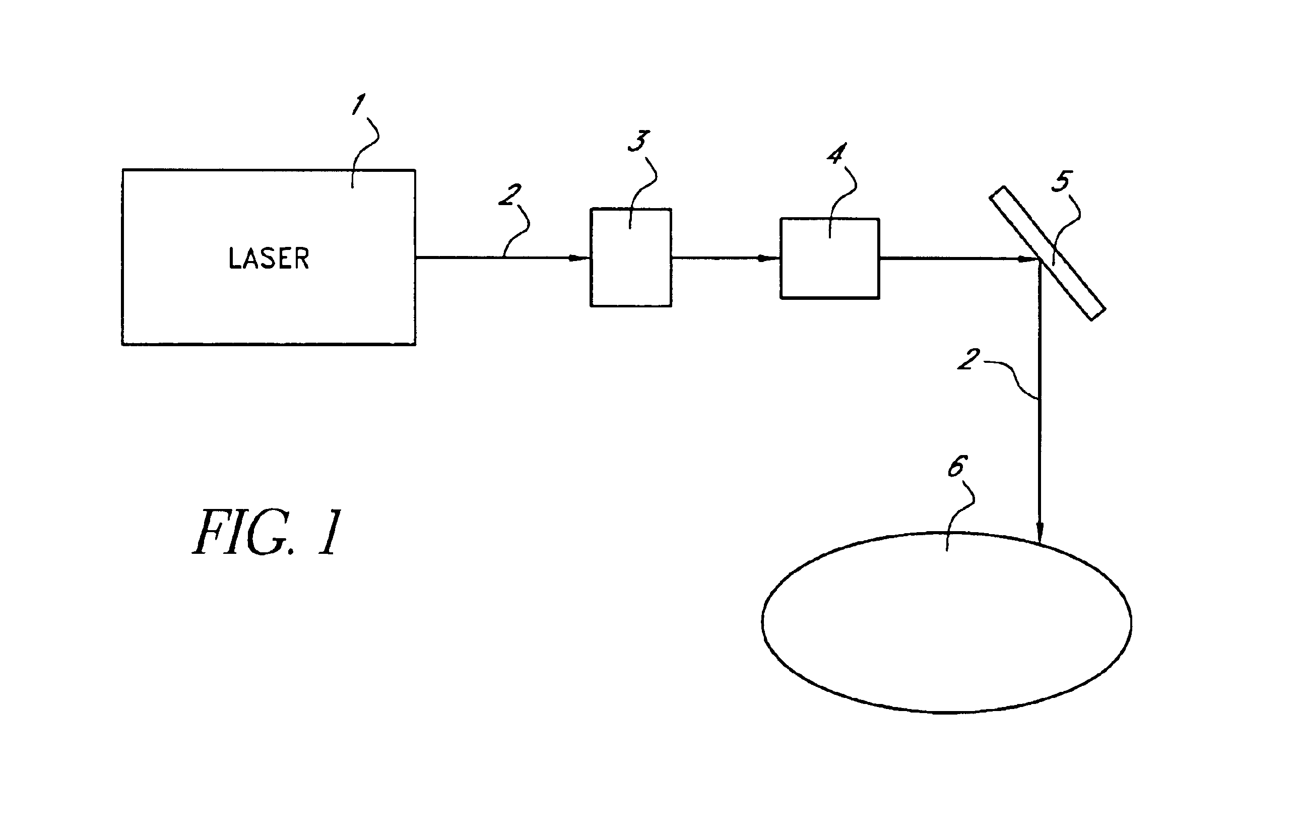
FIG. 1 of the drawings is a schematic of a laser system having an ablative laser 1 producing a laser beam 2 of a predetermined wavelength and focused by a lens 3 which is directed onto a scanner 4 and then reflected by a mirror 5 onto the cornea 6 of a patient's eye. The scanner 4 consists of a pair of motorized coated mirrors with a 45 degree highly reflecting both the ablative laser beam 2. The mirrors 4 is highly reflective to the wavelength of the beams 2. The focusing lens 3 has a focal length of about 10-100 cm such that the spot size of the ablative laser beam 2 is about 0.1-1.0 mm on the corneal surface. In FIG. 1, the ablative laser beams 2 is scanned by the scanner 4 over the corneal sclera area of the eye 6 to generate predetermined patterns. An alternative embodiment of the present surgical laser is to use a cylinder lens to focus the ablative laser 1 to a line spot with a size of 0.1-0.8 mm.times.3.0-5.0 mm on the corneal surface to eliminate the need of scanner 4. Furt...


PUM


Abstract

Presbyopia is treated by a method which uses various lasers to remove a portion of the scleral tissue and increase the accommodation of the presbyopic patient's eye. Stable accommodation is achieved by the filling of the sub-conjunctival tissue to the laser-ablated scleral areas. The proposed laser wavelength ranges from ultraviolet to infrared of (0.15-0.36) microns, (0.5-1.4) microns and (0.9-10.6) microns. Both scanning and fiber delivered systems are proposed.

Description

1. Field of the InventionThe present invention relates to apparatus and methods for the treatment of presbyopia using scanning and fiber-coupled lasers to ablate the sclera tissue.2. Prior ArtCorneal reshaping, including a procedure called photorefractive keratectomy (PRK) and a new procedure called laser assisted in situ keratomileusis, or laser intrastroma keratomileusis (LASIK), has been performed by lasers in the ultraviolet (UV) wavelength of 193-213 nm. Commercial UV refractive lasers include ArF excimer lasers at 193 nm and other non-excimer, solid-state lasers, such as the one patented by the present inventor in 1992 (U.S. Pat. No. 5,144,630). Precise, stable corneal reshaping requires lasers with strong tissue absorption (or minimum penetration depth) such that the thermal damage zone is at a minimum (less than few microns). Furthermore, accuracy of the procedure of vision correction depends on the amount of tissue removed in each laser pulse, in the order of about 0.2 micr...

Claims


Application Information

Patent Timeline
Patent Type & Authority Patents(United States)
IPC IPC(8): A61F9/01A61F9/007
CPCA61F9/008A61F9/00808A61F9/00838A61F9/00781A61F2009/00865A61F2009/00872A61F2009/00895
Inventor LIN, J. T.
Owner NEOS OCULAR
Why Eureka
Try Eureka