Laser scanning apparatus and methods for thermal processing

a scanning apparatus and thermal processing technology, applied in the direction of lasers, metal working apparatus, manufacturing tools, etc., can solve the problems of large laser and associated power supply needed to provide such high energy, substantial temperature variations, and inability to extend laser pulse lengths

Inactive Publication Date: 2004-06-08
VEECO INSTR
View PDF7 Cites 253 Cited by
  • Summary
  • Abstract
  • Description
  • Claims
  • Application Information

AI Technical Summary

Problems solved by technology

However the shorter the radiation pulse, the shallower the region that can be heat-treated, and the more likely that the circuit elements themselves will cause substantial temperature variations.
However, it is impractical to extend laser pulse lengths over periods longer than a microsecond and over circuit areas of 5 cm.sup.2 or more because the energy per pulse becomes too high, and the laser and associated power supply needed to provide such high energy becomes too big and expensive.
Unfortunately, the absorption depth for a typical laser diode operating at wavelength of 0.8 micron is about 20 microns for room temperature silicon.
This increases the total power required.
While a thin absorptive coating could be used to reduce this problem, it adds complexity to what is already a rather involved manufacturing process.
In practice, line image 100 is not entirely uniform because of diffraction effects.

Method used


Image

  • Laser scanning apparatus and methods for thermal processing
  • Laser scanning apparatus and methods for thermal processing
  • Laser scanning apparatus and methods for thermal processing

Examples


Embodiment Construction

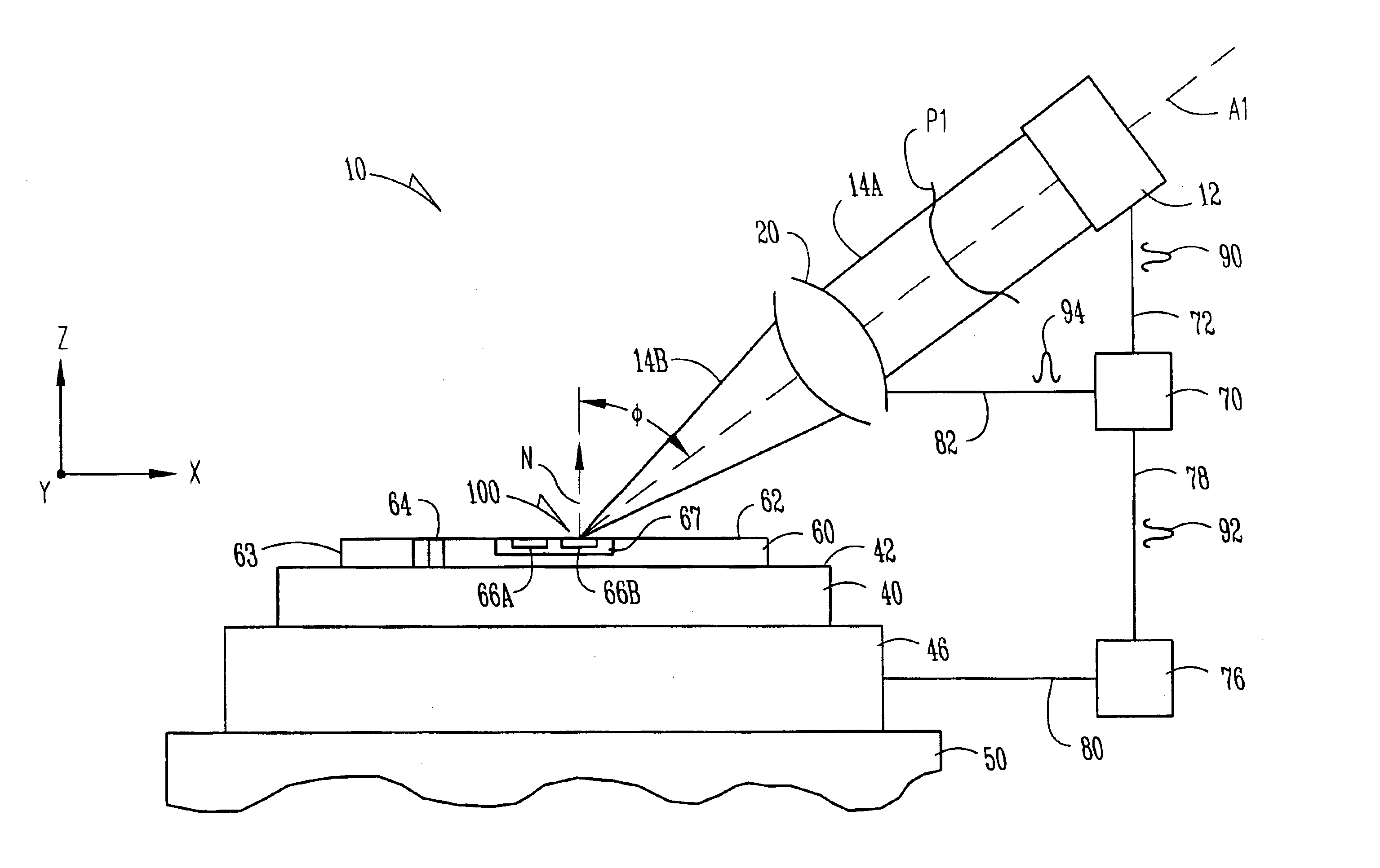
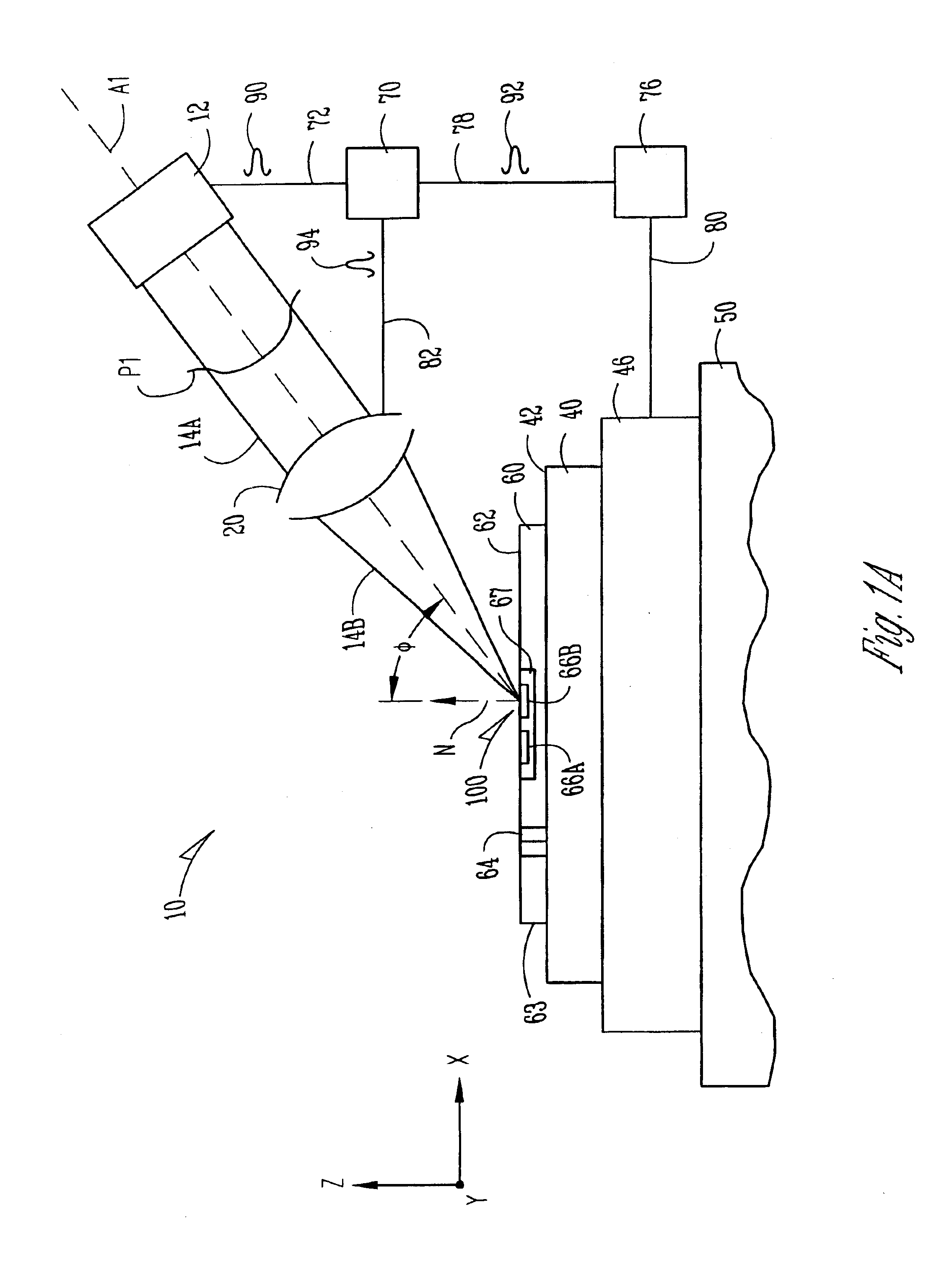
FIG. 3 is a schematic diagram of apparatus 10 similar to that of FIG. 1A that further includes a number of additional elements located across the top of the figure and above substrate 60. These additional elements either alone or in various combinations have been included to illustrate additional example embodiments of the present invention. It will be apparent to those skilled in the art how many of the additional elements introduced in FIG. 3 are necessary for the operation to be performed by each of the following example embodiments, and whether the elements discussed in a previous example embodiment is also needed in the embodiment then being discussed. For simplicity, FIG. 3 has been shown to include all of the elements needed for these additional example embodiments since some of these embodiments do build on a previously discussed embodiment. These additional example embodiments are discussed below.

Attenuator

With reference to FIG. 3, in one example embodiment, apparatus 10 in...


PUM

PropertyMeasurementUnit
wavelengthaaaaaaaaaa
incident angleaaaaaaaaaa

Abstract

Apparatus and methods for thermally processing a substrate with scanned laser radiation are disclosed. The apparatus includes a continuous radiation source and an optical system that forms an image on a substrate. The image is scanned relative to the substrate surface so that each point in the process region receives a pulse of radiation sufficient to thermally process the region.

Description

1. Field of the InventionThe present invention relates to apparatus and methods for thermally processing substrates, and in particular semiconductor substrates with integrated devices or circuits formed thereon.2. Description of the Prior ArtThe fabrication of integrated circuits (ICs) involves subjecting a semiconductor substrate to numerous processes, such as photoresist coating, photolithographic exposure, photoresist development, etching, polishing, and heating or "thermal processing." In certain applications, thermal processing is performed to activate dopants in doped regions (e.g., source and drain regions) of the substrate. Thermal processing includes various heating (and cooling) techniques, such as rapid thermal annealing (RTA) and laser thermal processing (LTP). Where a laser is used to perform thermal processing, the technique is sometimes called "laser processing" or "laser annealing."Various techniques and systems for laser processing of semiconductor substrates have b...

Claims


Application Information

Patent Timeline
Patent Type & Authority Patents(United States)
IPC IPC(8): B23K26/02B23K26/073B23K26/03B23K26/08B23K26/00B23K26/06B23K26/04
CPCB23K26/032B23K26/04B23K26/0738B23K26/08H01L21/268B23K26/0807H01L21/67115B23K2201/40H01L21/02683H01L21/02691B23K26/082B23K2101/40H01S3/10
Inventor TALWAR, SOMITTHOMPSON, MICHAEL O.MARKLE, DAVID A.
Owner VEECO INSTR
Why Eureka
Try Eureka