Thermal treatment apparatus

a treatment apparatus and treatment method technology, applied in the field of thermal treatment apparatus, can solve the problems of inability to detect abnormalities, used to be a danger of damaging the laser emission part or the endoscope, and required complex procedures in order, and achieve excellent treatment effect and good reciprocating motion of the energy emission par

Inactive Publication Date: 2004-07-20
TERUMO KK +1
View PDF13 Cites 8 Cited by
  • Summary
  • Abstract
  • Description
  • Claims
  • Application Information

AI Technical Summary

Benefits of technology

It is an object of the present invention to provide a thermal treatment apparatus that is capable of providing a good reciprocating motion of the energy emission part and achieving an excellent treatment effect by properly applying energy to the lesion of the object.

Problems solved by technology

Thus, it used to require complex procedures in order to make observations by means of the endoscope.
Furthermore, there used to be a danger of damaging the laser emission part or the endoscope, if the endoscope is moved toward the distal side of the insertion unit by mistake, when the laser emission part is not in the retracted position.
However, there has been a problem that, when some damages or separations occur in the connecting mechanism between the motor and the laser emission part, the abnormality cannot be detected even though the abnormality results in a problem of the reciprocating motion of the laser emission part.
This makes it very difficult to make a judgment how long irradiation time needs to be added in order to achieve a proper treatment effect as the temperature of the tissue, which has been heated by applying energy, lowers while the irradiation time is being reset.
Moreover, since the thermal treatment requires procedures in a sterilized area, the equipment used repeatedly for setting the energy power and the irradiation time, which is difficult to maintain a sterilized condition, is placed outside of the sterilized area.
Therefore, the user who is in a sterilized area cannot reset the irradiation time directly.
This means that the user has to ask another person to reset the irradiation time, so that the user cannot reset the irradiation time based on an instant decision and may not be able to perform treatments adequately.
This caused a problem of instability in the heating performance for the treatment as the energy irradiated on the living body varies with the energy irradiation unit even if the energy generated by the energy supply unit is maintained constant.
This apparatus may not be able to perform accurate measurements as the operator has to measure the energy irradiated by the energy irradiation unit.
Moreover, even if it is possible make an accurate measurement, it is extremely difficult to measure energy without causing contamination of the energy irradiation unit using an unsterilized measuring device.
Under such a circumstance, it used to require very complex procedures such as the necessity of preparation of a port member or a connecting member in order to prevent contaminations.

Method used


Image

  • Thermal treatment apparatus
  • Thermal treatment apparatus
  • Thermal treatment apparatus

Examples


first embodiment

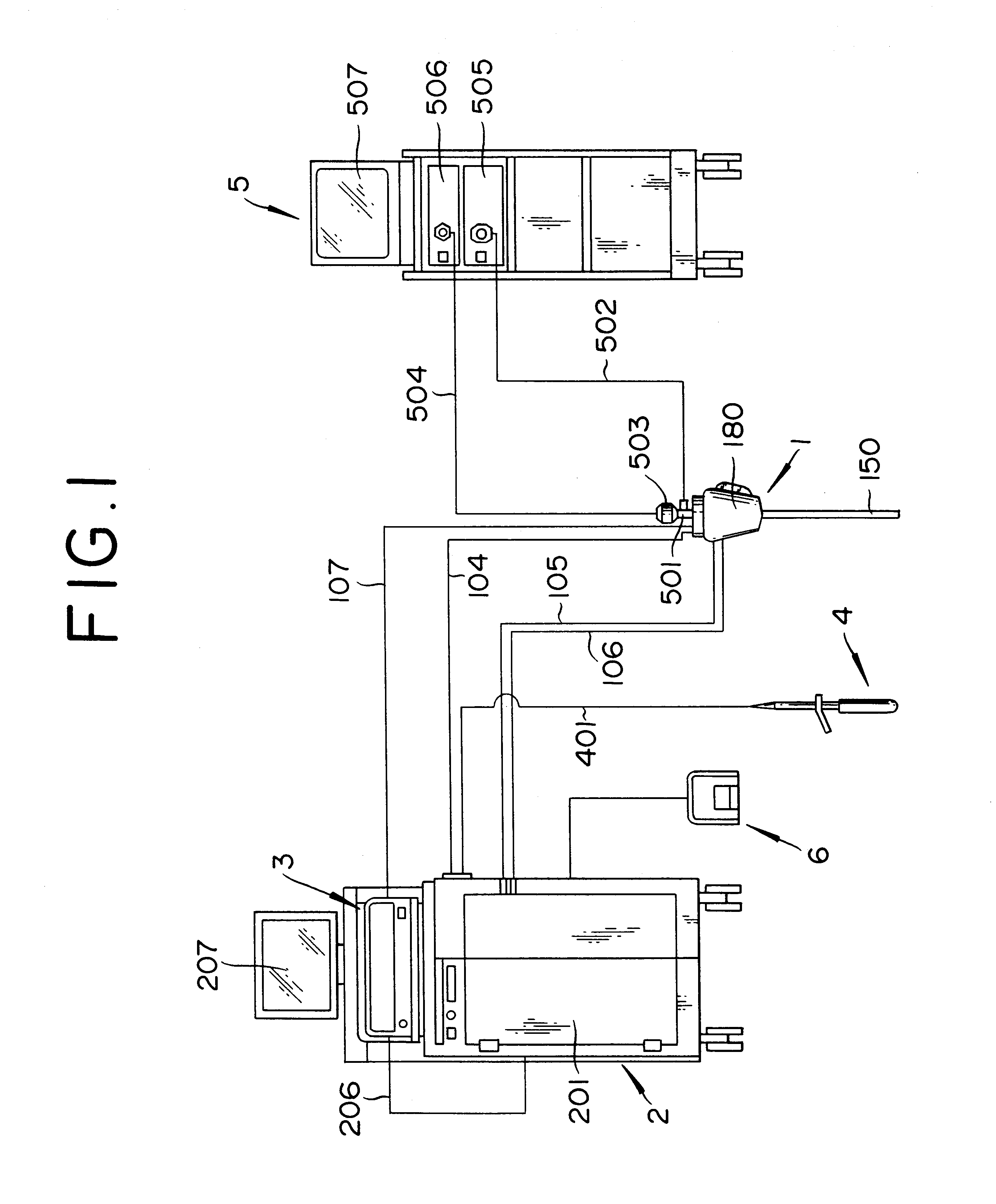
[Embodiment 1] FIG. 1 shows a system constitution of a thermal treatment apparatus according to the invention.

The thermal treatment apparatus of the present embodiment includes a laser irradiation unit (urethra probe) 1 as an energy irradiation unit, a main controller 2, a laser generator 3 as an energy supply unit, a rectum probe 4, a foot switch 6 as an irradiation operating unit, and an endoscopes system 5. The laser irradiation unit 1, the laser generator 3, the rectum probe 4, and the foot switch 6 are all connected to the main controller 2. The foot switch 6 outputs a signal to prompt the main controller 2 to start laser beam irradiation when the operator steps it on.

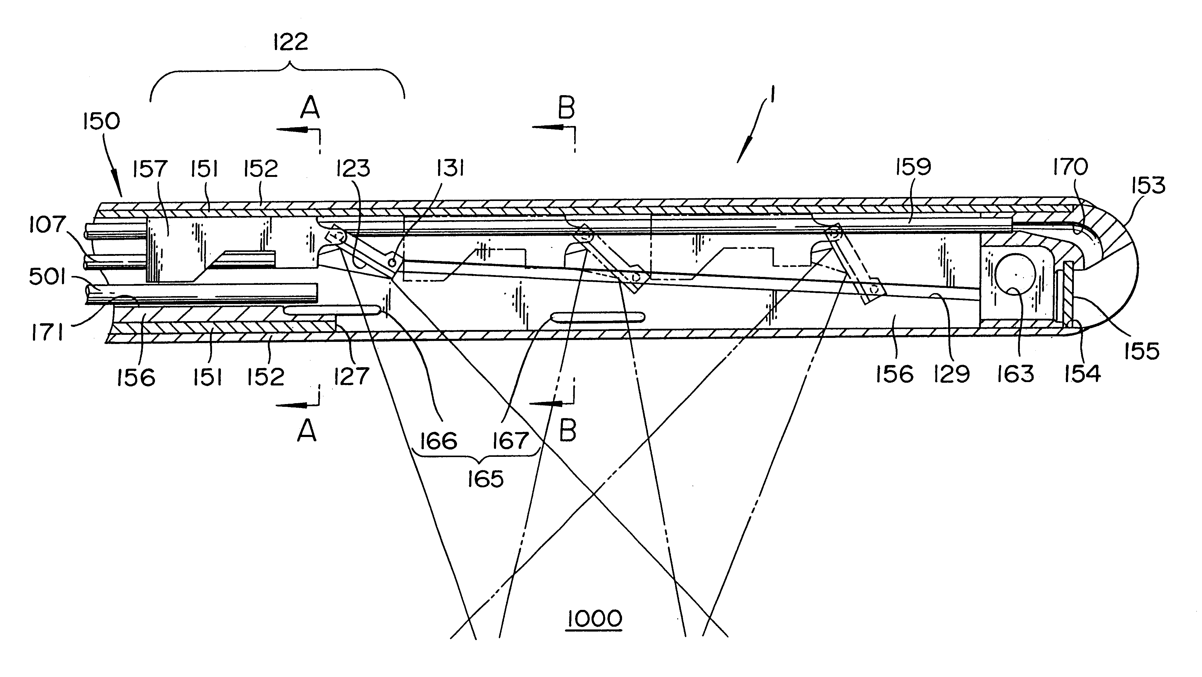
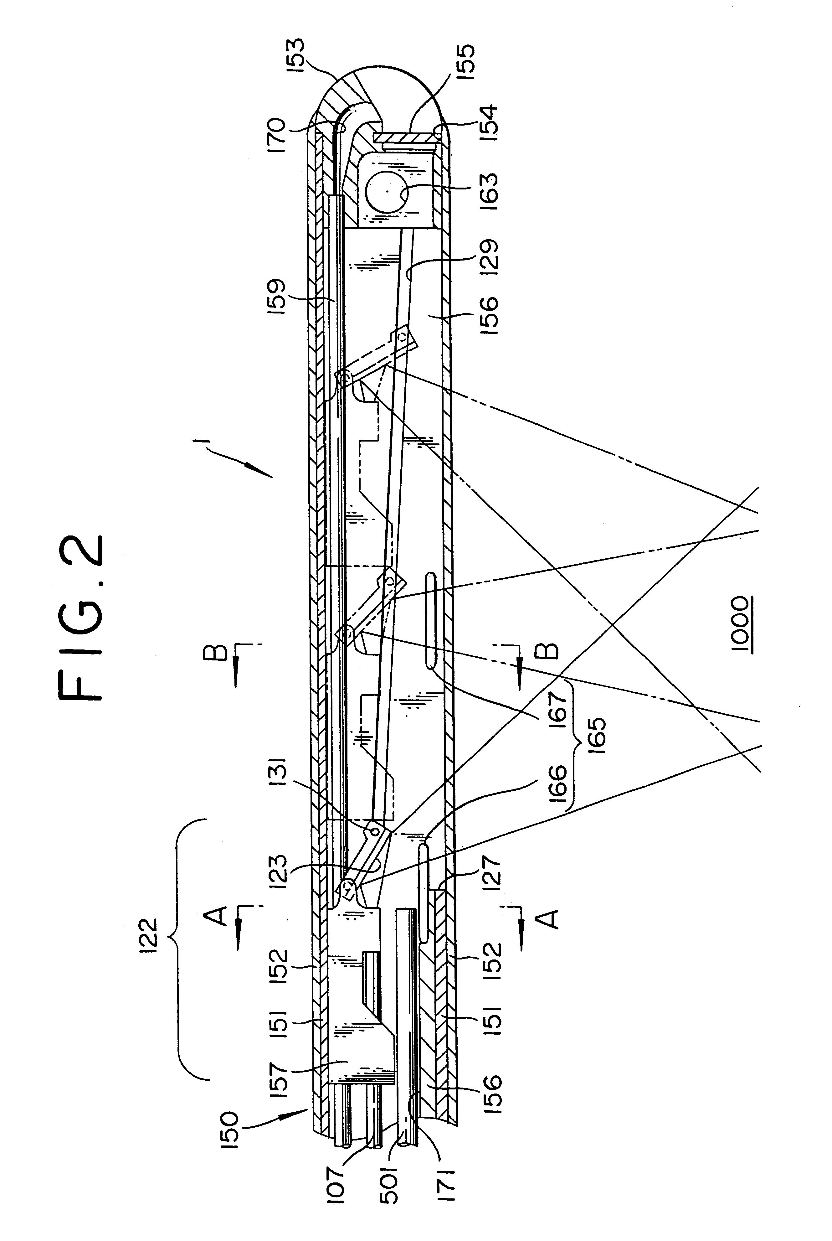
FIG. 2 shows a cross section of the distal part of a laser irradiation unit, FIG. 3 is a schematic bottom view of FIG. 2, FIG. 4 is a cross sectional view along line A--A of FIG. 2, and FIG. 5 is a cross sectional view along line B--B of FIG. 2.

The laser irradiation unit 1 of the present embodiment is a laser irra...

embodiment 2

[Embodiment 2] FIG. 13 and FIG. 14 are flowcharts indicating the control sequence for the moving laser beam irradiation of the thermal treatment apparatus according to a second embodiment. The second embodiment will be described bellow primarily concerning with the differences from the first embodiment while omitting descriptions on common parts.

The second embodiment is different from the first embodiment in that it has, in addition to the emission part position sensor 181 that detects that the laser emission part 122 is located at the proximal position (position indicated by solid lines in FIG. 2), another emission part position sensor (not shown), e.g., a photo-interrupter, which detects that the laser emission part 122 is located at the distal position (the one on the right side of the two positions indicated by phantom lines in FIG. 2), is provided in the proximal unit 180. Other constitutions of the thermal treatment apparatus of this embodiment are identical to those of the fi...

embodiment 3

[Embodiment 3] FIG. 15 is a cross sectional view of the distal part of the laser irradiation unit used on a thermal treatment according to a third embodiment and FIG. 16 is a schematic bottom view of FIG. 15. The third embodiment will be described bellow primarily concerning with the differences from the first embodiment while omitting descriptions on common parts.

The laser irradiation unit 1a of the third embodiment is different from that of the first embodiment in that the reciprocating motion detection sensor 166 of the detection unit 165a is located in the vicinity of the distal position of the reciprocating motion of the laser emission part 122, i.e., the vicinity of the front end of the window 127. This makes it possible, as shown in FIG. 15, to detect the laser beam emitted by the laser emission part 122 when the laser emission part 122 is at the distal position (the right side one of the two positions shown by phantom lines in FIG. 15). Other constitutions of the thermal tre...


PUM


Abstract

The thermal treatment apparatus is equipped with a laser generator for supplying laser beams, a laser irradiation unit for applying the supplied laser beams to tissues, and a control unit for totally controlling various parts of the system. The laser irradiation unit is equipped with a movable laser emission part for emitting laser beams to tissues, a motor for reciprocating a laser emission part, and a guide lumen for supporting an endoscope in such a way as to enable it to move in the direction of the laser emission part. The control unit controls the motor that drives the laser emission part to make reciprocation motion in such a way that the laser emission part stops at a position where it does not interfere with the moving passage of the endoscope.

Description

1. Field of the InventionThe invention is related to a thermal treatment apparatus for thermally treating by inserting an insertion unit into a human body either via a body cavity or a lumen such as blood vessels, urethra and abdominal cavity, or pressing its pressing part against a vital tissue surgically or on the body surface, and then irradiating a vital tissue with the energy such as laser beam, microwave, radio frequency, and ultrasound from its emission part provided at the insertion unit or the pressing part.2. Description of the Related ArtVarious thermal treatment apparatuses have been know for treating lesions to reduce or eliminate them by means of heating, degeneration, necrosis, coagulation, cauterization or vaporization of lesions by irradiating them with the energy, such as laser beam, microwave, radio frequency, and ultrasound, with a long and slender insertion unit inserted into a living body either via a body cavity or an opening produced by a small incision.For e...

Claims


Application Information

Patent Timeline
Patent Type & Authority Patents(United States)
IPC IPC(8): A61B18/20A61B18/22A61B18/00A61B19/00A61B17/00A61B18/18A61F7/12A61N5/02A61N5/06
CPCA61B18/22A61B19/5202A61B19/5212A61B2017/00084A61B2018/00023A61B2018/00196A61B2018/00982A61B2018/2283A61B90/30A61B90/361
Inventor HAREYAMA, NORIHIKOUESUGI, TAKEFUMISATO, TAISUKEIWAHASHI, SHIGENOBUARIURA, SHIGEKIKARINO, WATARUINABA, MAKOTOMAKI, SHIN
Owner TERUMO KK
Why Eureka
Try Eureka