
Image integration and multiple laser source projection

a laser source and integrated technology, applied in the field of image integration and multiple laser source projection, can solve the problems of limiting the allowed aperture dimension and overall design complexity, no system now available allows for the combination of the various functions required, and reducing the cost of reradiation

Inactive Publication Date: 2004-08-10
UNITED STATES OF AMERICA THE AS REPRESENTED BY THE SEC OF THE ARMY
View PDF8 Cites 13 Cited by
  • Summary
  • Abstract
  • Description
  • Claims
  • Application Information

AI Technical Summary

Benefits of technology

When the electro-optical devices are light emitters, the lens assembly and faceted diverting means produce a single output beam representing the characteristics of all the emitters. The emitters can be identical resulting only in a more intense beam, e.g. in a LIDAR echo ranging system, or as a simple target designator for a weapon system. In both system the efficiency and reliability is improved by using emitters of different light wavelengths and or modulating them with codes that represent classes or specific targets and / or their most effective deterrent weapon systems.

Problems solved by technology

No system now available allows for the combination of the various functions required for providing a fully functional and practical ATR system.
Enhancements to the SNR are more difficult, however, because most detectors cannot simply "boost" their signal levels without also increasing the noise present; and the latter is fixed by practical limits on the allowed aperture dimensions and overall design complexity.
In imagers currently available, this puts more pixels on the target, but can result in an increased f-number and pixels that have more noise.
This technique requires complex timing on the array readout, and obviously involves more complicated manufacturing processes to include the extra arrays.
TDI is not practical for a two-dimensional staring array because it relies upon some method of scanning the scene.
The problem with this technique is that neither the sensor nor target can be in relative motion; otherwise the shifts of object location, on the focal plane over time, will smear out image details as frames of imagery are summed over time.
Designators become more complex as multiple random factors and multiple targets make it harder for a weapon to acquire its intended target.
The extremely short time intervals utilized for weapon execution also complicate designation.
If two high cost weapon systems attack the same target, this is an unnecessary waste battlefield resources.
For imaging sensors, illumination appears to be an ideal technique, but has not yet been practically demonstrated.
This places a practical limitation on the output power that can be directed at a small target some distance away from the illuminator.
Mismatches between the individual and combining optics often lead to additional distortion problems.
While the prior art has reported using enhancement of sensor resolution and target designation, none have established a basis for a specific apparatus and technique that is dedicated to the task of solving the particular problem addressed by applicant.

Method used


Image

  • Image integration and multiple laser source projection
  • Image integration and multiple laser source projection
  • Image integration and multiple laser source projection

Examples


Embodiment Construction

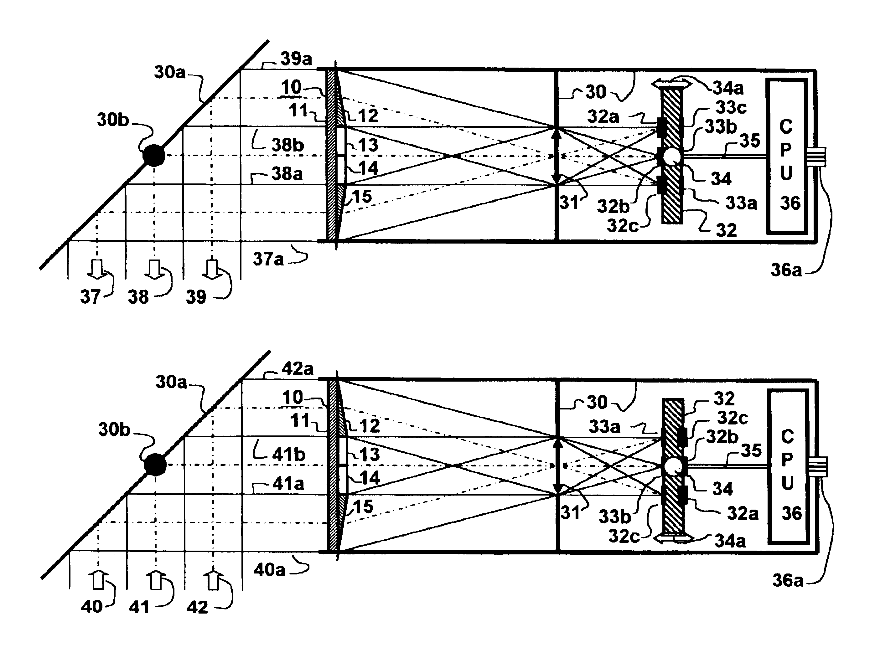
The invention described herein provides a method and apparatus for improving the efficiency of target sensor and / or designator devices. The sensor devices may be level sensitive photo-diodes used as pixel detectors in electro-optical imaging devices or the less discriminating, but more sensitive photo-multiplier type Infrared Search and Track (IRS&T) sensors, which detect and display distant targets as a moving points. Both photo-diodes and laser diodes are inherently small, so that thousands can be placed on a one-inch square substrate with their photo-active surfaces defining a focal plane. Larger devices that are more sensitive or powerful can be coupled through a bundle of optical glass fibers the ends of which define a similarly small area of a focal plane.

There is described herein a sensor resolution enhancement scheme that does not sacrifice time resolution, but simultaneously and optically projects several identical narrow fields of view (NFV)s onto a system focal plane that...


PUM


Abstract

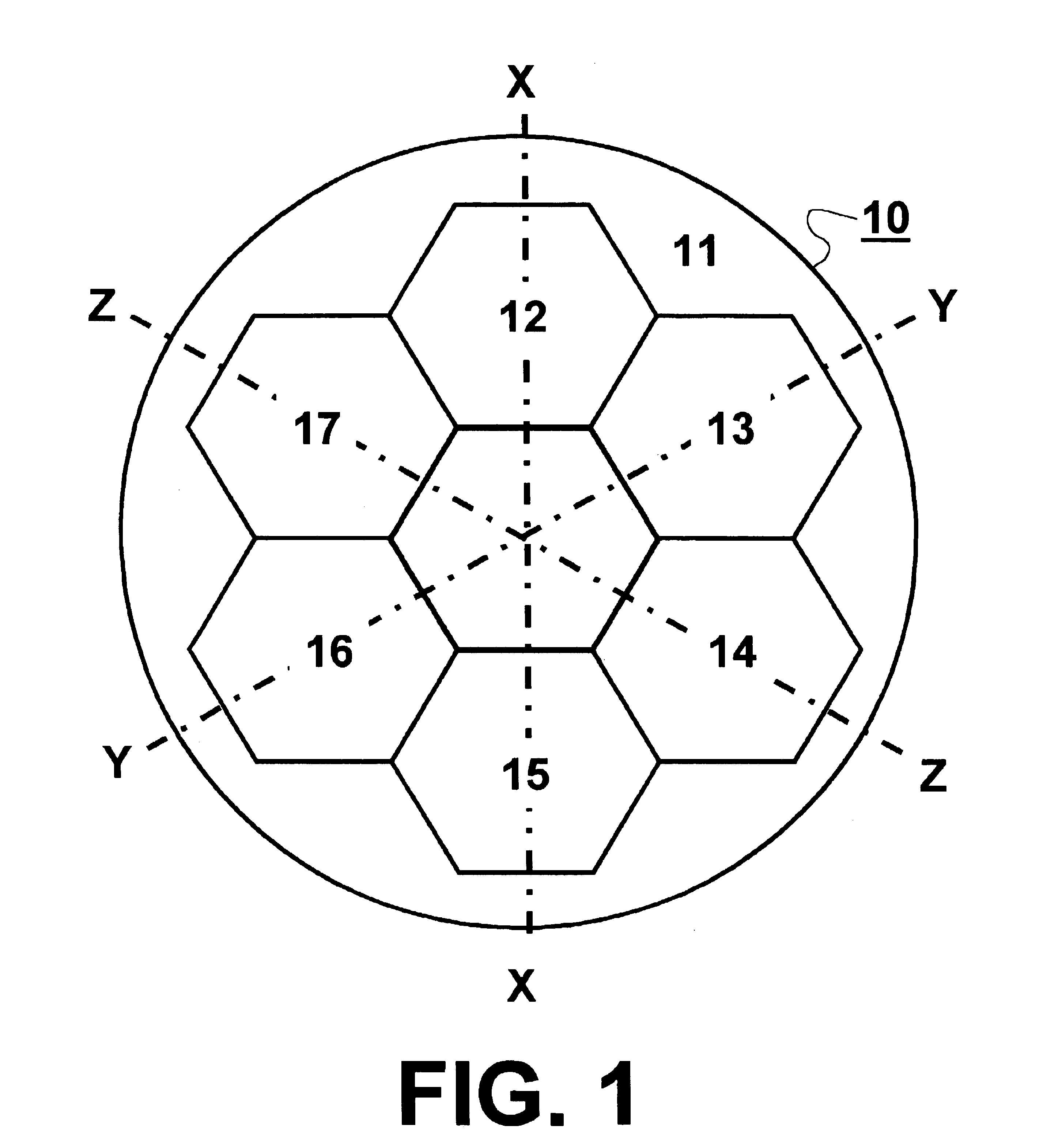
An apparatus and method for enhancing an image relayed by a central beam of collimated light centered on the optical axis of a lens with an aperture area of A and focused on the focal plane of the lens. The apparatus having an aperture at least n times as big as A centered on the optical axis of the lens to admit a collimated relay beam including the central beam and a diverter means for separating the relay beam into n collimated facet beams equal to the central beam, but exclusive thereof, and redirecting them through the lens aperture to produce n additional images on the same focal plane. The apparatus also including a processor with a separate opto-electronic device for each image that converts it between electronic and photonic states, the electronic images being stored in the processor.

Description

1. Field of the InventionThe present invention generally relates to an apparatus for improving signal-to-noise ratio and / or resolution of opto-electronic target image detection systems as well as the reliability and versatility of similar laser designator systems More specifically, the present invention adds a multi-faceted optical diverter in a system using a lens with a given aperture to focus one central beam of collimated light with a cross-section matching that aperture as it travels between a target and at least one opto-electonic device such as a laser or detector diode located at the focal point of the lens in its focal plane. The diverter includes facets that redirect similar collimated facet beams adjacent and parallel to the central beam which pass through the same lens aperture between the same target and a separate set of facet opto-electronic devices. These facet devices are located at other focal points of the lens in the same focal plane. The combination of all these...

Claims


Application Information

Patent Timeline
Patent Type & Authority Patents(United States)
IPC IPC(8): G21K1/00G21K1/06
CPCG01S7/4816G01S17/89
Inventor FRIEDMAN, MELVIN H.HALL, JOHN M.
Owner UNITED STATES OF AMERICA THE AS REPRESENTED BY THE SEC OF THE ARMY
Learn More