
Method and apparatus for generating high output power gas discharge based source of extreme ultraviolet radiation and/or soft x-rays

a technology of ultra-violet lithography and gas discharge, which is applied in the field of ultra-violet lithography to achieve the effect of preventing electrode burnout and reducing the influence of reflection

Inactive Publication Date: 2004-10-12
USHIO DENKI KK
View PDF90 Cites 90 Cited by
  • Summary
  • Abstract
  • Description
  • Claims
  • Application Information

AI Technical Summary

Benefits of technology

The present invention relates to an improved extreme ultraviolet (EUV) lithography tool for use in industrial applications such as photolithography. The invention provides an improved EUV photon source with output emission characteristics more suitable for industrial applications. The invention includes a plasma chamber filled with a gas mixture, multiple electrodes, a power supply circuit, and a preionizer for ionizing the gas mixture. The invention also includes an ionization unit, baffles, a clipping aperture, and a reflecting surface for outputting the EUV beam. The technical effects of the invention include improved beam quality, reduced contamination, and improved efficiency of the photon source.

Problems solved by technology

The rapid collapse of the shell results in collisions between all portions of the incoming shell at the central axis with radially opposed portions of the incoming shell.

Method used


Image

  • Method and apparatus for generating high output power gas discharge based source of extreme ultraviolet radiation and/or soft x-rays
  • Method and apparatus for generating high output power gas discharge based source of extreme ultraviolet radiation and/or soft x-rays
  • Method and apparatus for generating high output power gas discharge based source of extreme ultraviolet radiation and/or soft x-rays

Examples


sixth embodiment

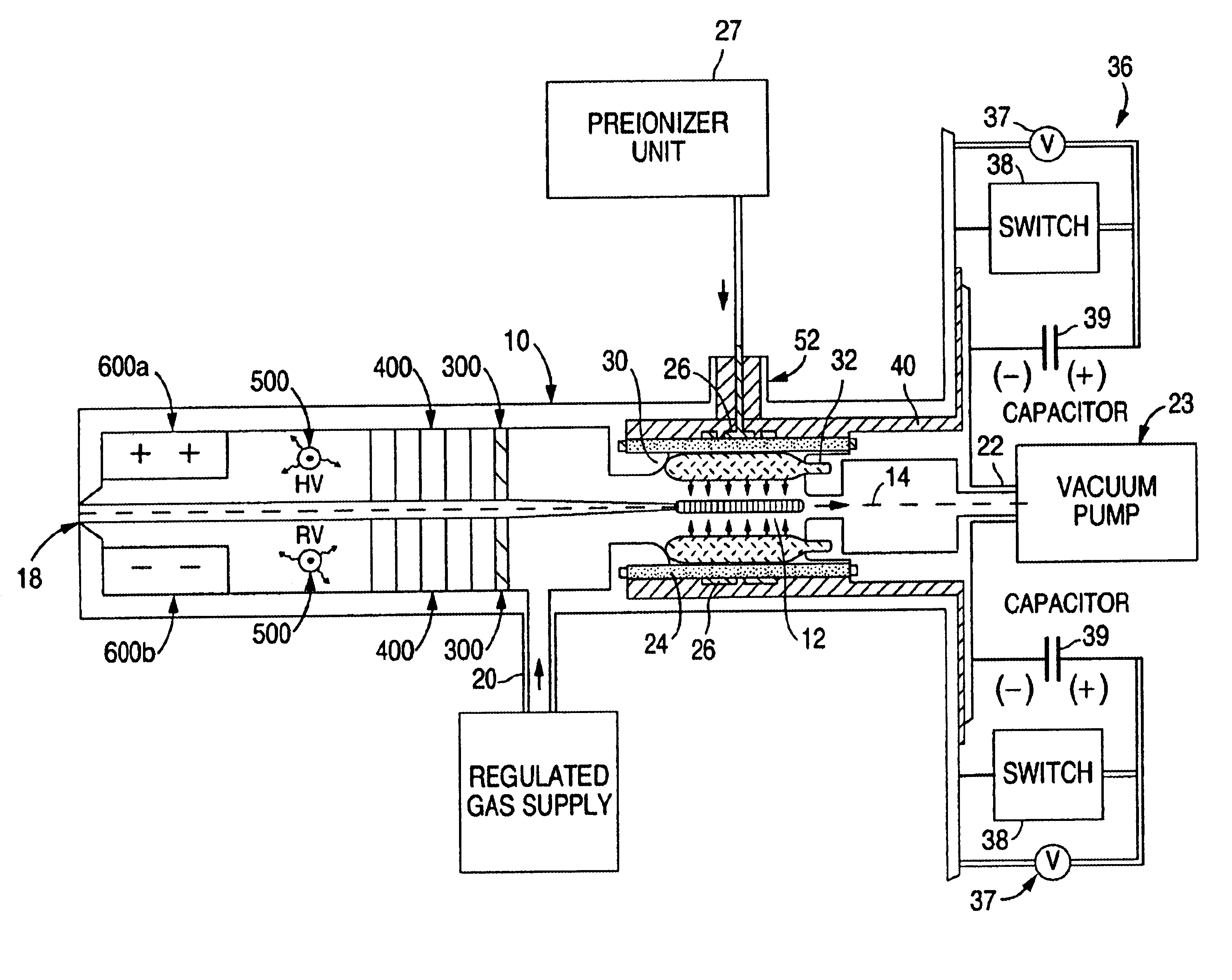
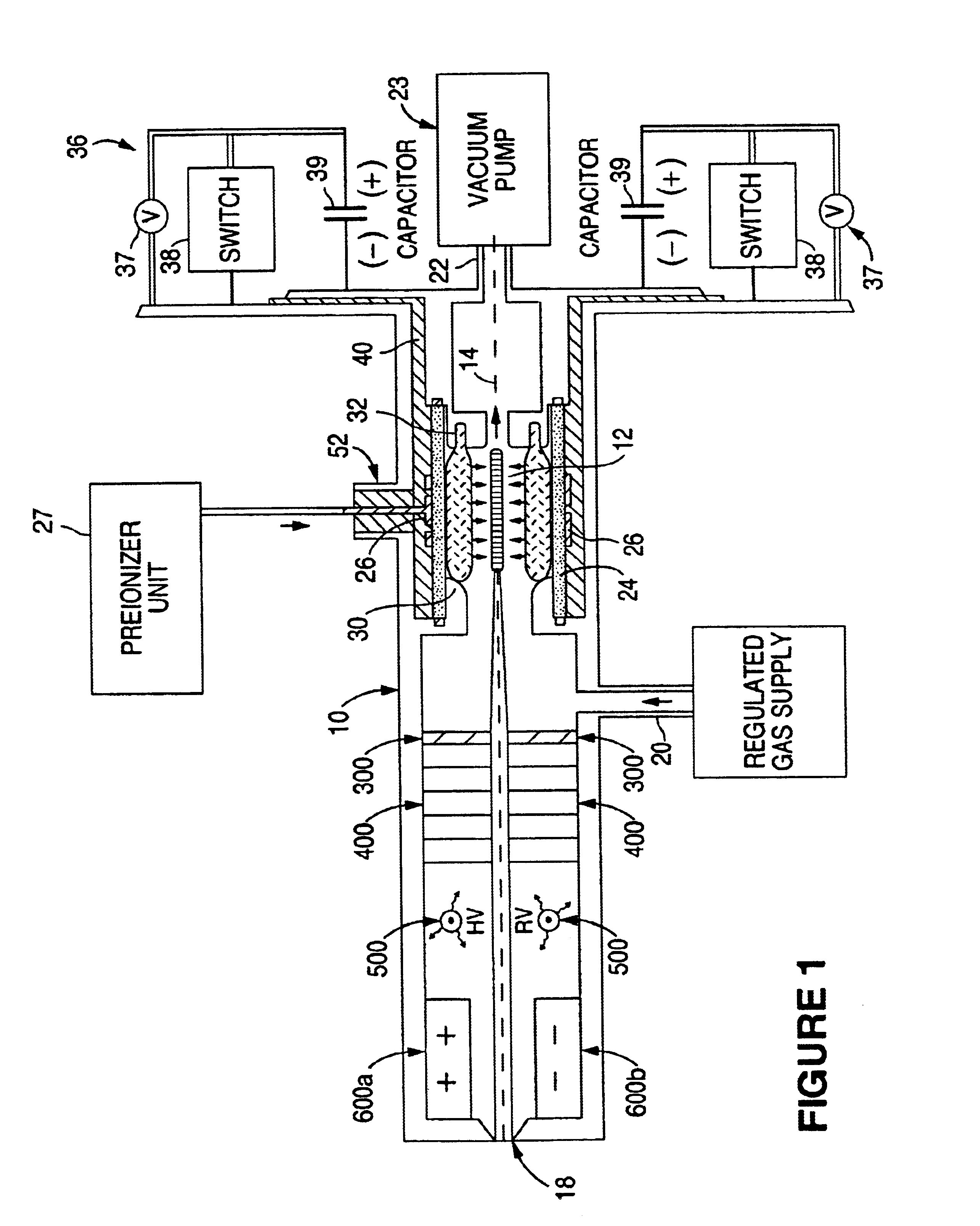
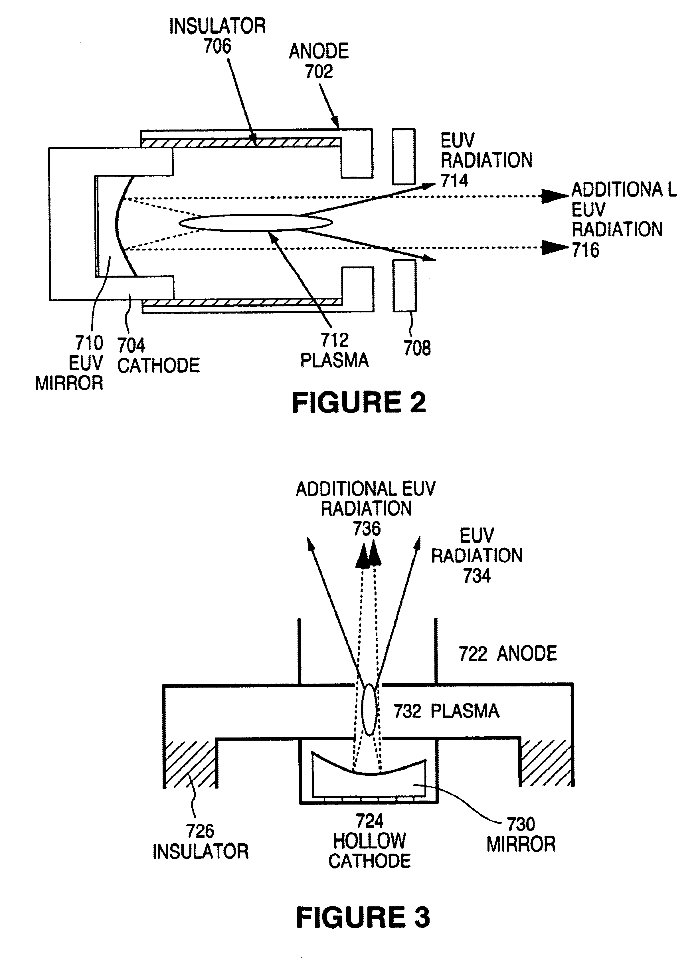
FIG. 2 schematically illustrates an EUV generating source, and particularly a Z-pinch device, including a reflecting surface opposite a beam output side of the central axis according to a The EUV source schematically shown at FIG. 2 includes an anode 702 and a cathode 704 electrically separated by an insulator 706. The exemplary and illustrative Z-pinch device shown at FIG. 2 also includes a clipping aperture 708 for matching and / or defining a divergence for the EUV beam. The clipping aperture 708 may include one or more features of the aperture 300 of FIG. 1. Although not shown at FIG. 2, the Z-pinch device may also include any of baffles 400, ionizer 500 and precipitator 600a, 600b described with reference to the system shown at FIG. 1, e.g., after the clipping aperture 708, 300 along the EUV beam path. The EUV source of FIG. 2 further includes an EUV mirror 710 or EUV reflecting surface 710.

In operation, the Z-pinch EUV source of FIG. 2 rapidly generates a dense plasma 712, e.g....

seventh embodiment

FIG. 3 schematically illustrates an EUV generating source, and particularly a hollow cathode triggered (HCT) pinch device, including a reflecting surface opposite a beam output side of the central axis according to a The exemplary and illustrative HCT-pinch EUV source schematically shown at FIG. 3 includes an anode 722 and a hollow cathode 724 electrically separated by an insulator 726. Although not shown at FIG. 3, the HCT-pinch device may also include any of clipping aperture 300, baffles 400, ionizer 500 and precipitator 600a, 600b described with reference to FIG. 1. The EUV source of FIG. 3 further includes an EUV mirror 730 or EUV reflecting surface 730.

In operation, the HCT-pinch EUV source of FIG. 3 rapidly generates a dense plasma 732, when a potential difference is applied to the electrodes 722, 724. EUV radiation 714 emanates from the dense plasma 732 particularly in each of the two opposing, axial directions (i.e., to the top and to the bottom of the page in FIG. 3). On ...

eighth embodiment

FIG. 4 schematically illustrates an EUV generating source, and particularly a capillary discharge (CD) device, including a reflecting surface opposite a beam output side of the central axis according to a The exemplary and illustrative capillary discharge EUV source schematically shown at FIG. 4 includes an anode 742 and a cathode 744 electrically separated by an insulator 746 including a capillary 747 within which a plasma 752 is created. The capillary discharge device shown at FIG. 4 also includes a clipping aperture 748 for matching and / or defining a divergence for the EUV beam. The clipping aperture 748 may include one or more features of the aperture 300 of FIG. 1 and / or the aperture 708 of FIG. 2. The gases used to form the plasma 752 of the device of FIG. 4, as well as for the devices of FIGS. 1 and 3-5, or another device in accordance with a preferred embodiment, may be supplied through gas supply 758, as shown, or otherwise as understood by those skilled in the art. Althou...


PUM

PropertyMeasurementUnit
at-wavelength aaaaaaaaaa
reflectivityaaaaaaaaaa

Abstract

The method and system herein pertain to an EUV photon source which includes a plasma chamber filled with a gas mixture, multiple electrodes within the plasma chamber defining a plasma region and a central axis, a power supply circuit connected to the electrodes for delivering a main pulse to the electrodes for energizing the plasma around the central axis to produce an EUV beam. The system can also include a preionizer for ionizing the gas mixture in preparing to form a dense plasma around the central axis upon application of the main pulse from the power supply circuit to the electrodes. A set of baffles may be disposed along the beam path outside of the pinch region to diffuse gaseous and contaminant particulate flow emanating from the pinch region and to absorb or reflect acoustic waves emanating from the pinch region away from the pinch region.

Description

1. Field of the InventionThe present invention relates to extreme ultraviolet (EUV) lithography, and particularly to an EUV radiation source configured for transmitting an improved EUV beam.2. Discussion of the Related ArtSemiconductor manufacturers are currently using deep ultraviolet (DUV) lithography tools based on KrF-excimer laser systems operating around 248 nm, as well as the following generation of ArF-excimer laser systems operating around 193 nm. Industrial applications in the Vacuum UV (VUV) range involve the use of the F.sub.2 -laser operating around 157 nm. EUV radiation sources for EUV lithography emitting 11-15 nm photon beams are currently being developed.EUV radiation sources have an advantageous output emission beam including 11-15 nm wavelength photons having photon energies greater than 90 eV. This short wavelength is advantageous for industrial applications, such as particularly photolithography, mask writing and mask and wafer inspection applications, because t...

Claims


Application Information

Patent Timeline
Patent Type & Authority Patents(United States)
IPC IPC(8): B03C3/38B03C3/34G03F7/20H05G2/00
CPCB03C3/383B82Y10/00H05G2/003G03F7/70175G03F7/70916G03F7/70033
Inventor SCHRIEVER, GUIDOREBHAN, ULRICH
Owner USHIO DENKI KK
Learn More