
System and method for multiple-phase clock generation

a multi-phase clock and clock generation technology, applied in the direction of generating/distributing signals, pulse techniques, counting chain synchronous pulse counters, etc., can solve the problems of layout and routing in the integrated circuit chip, the quality of a multi-phase clock degrades, and the technique suffers

Inactive Publication Date: 2004-10-26
UNIVERSAL CONNECTIVITY TECH INC
View PDF12 Cites 25 Cited by
  • Summary
  • Abstract
  • Description
  • Claims
  • Application Information

AI Technical Summary

Problems solved by technology

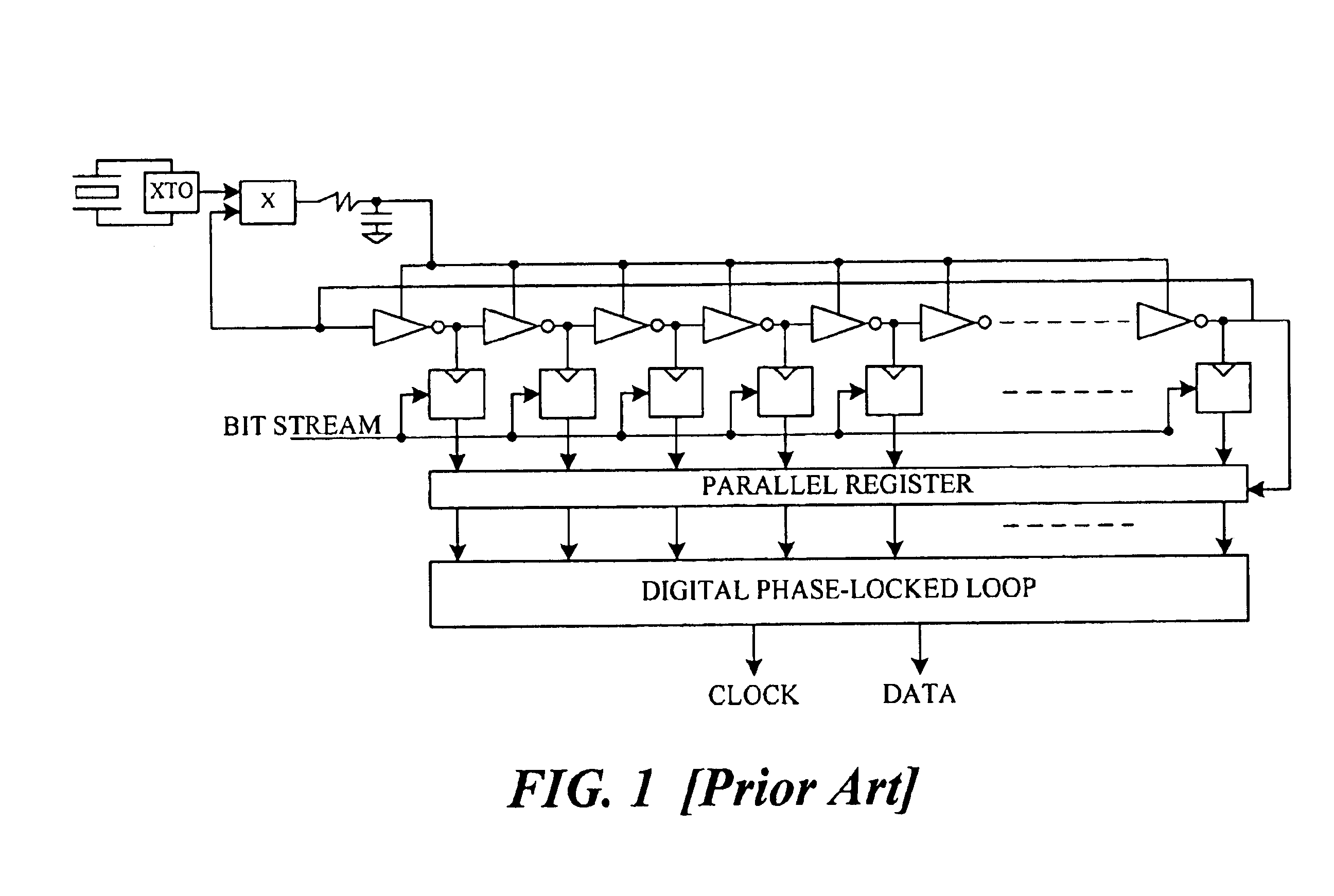
However, this technique suffers from a number of disadvantages in the environment just described.
More specifically, the quality of a multi-phase clock degrades as the number of clock phases increases.
Furthermore, generation of a larger number of multiple-phase clocks makes layout and routing more difficult in an integrated circuit chip.
Also like the ring-oscillator, as cells are added the precision of the multi-phase clock degrades, thereby placing a practical limit on how many cells can be added.
However, as the number of VCO cells increases, the power consumption and layout area necessary for multiple-phase bus routing also increase.
As a result, the optimum layout of a VCO and other sampling circuitry becomes increasingly difficult as the number of cells increases.
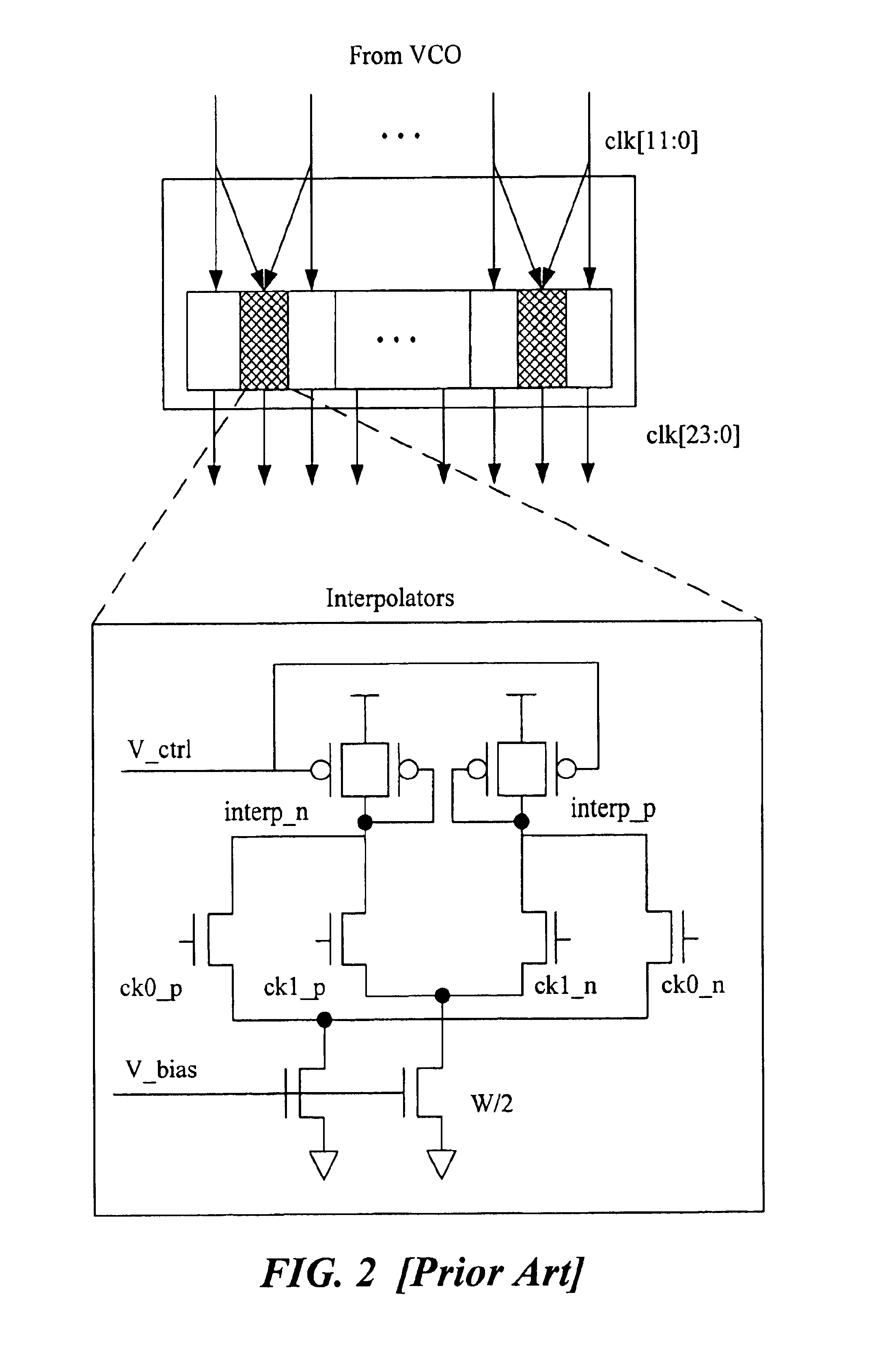
Unfortunately, this technique generates phase errors in the interpolated clocks.
For example, if a clock interpolator receives two clock signals, clock A and clock B, the resulting output becomes the interpolated values of clock A and clock B. Unfortunately, this technique generates errors which makes such an interpolated clock signal deviate from the ideal value.
This makes interpolator deviate from ideal location because the linear rule is no longer valid.
If the clock phases for the clock interpolator have bigger rise / fall times then the interpolated value is very close to ideal value, however, this increases the effect of offsets and noise in the interpolating circuit, which would eventually degrade the quality of signals generated by an associated phase-locked loop ("PLL").
To compensate for the noise increase, the power consumption of this device may be increased, but at the expense of eventually increasing the power consumption of the total system in which the device is embedded.
Therefore, to realize a wide range of operations using clock interpolation, the circuit complexity and power consumption becomes impractical at some point.

Method used


Image

  • System and method for multiple-phase clock generation
  • System and method for multiple-phase clock generation
  • System and method for multiple-phase clock generation

Examples


Embodiment Construction

The invention will now be described with respect to various embodiments. The following description provides specific details for a thorough understanding of, and enabling description for, these embodiments of the invention. However, one skilled in the art will understand that the invention may be practiced without these details. In other instances, well-known structures and functions have not been shown or described in detail to avoid unnecessarily obscuring the description of the embodiments of the invention. For each embodiment, the same reference numbers and acronyms identify elements or acts with the same or similar functionality for ease of understanding and convenience.

The problems and disadvantages described above are overcome by embodiments of the invention, which in at least one embodiment provides a multiple-phase clock capable of generating multiple clock phases with reduced noise and simplified chip layout characteristics. The invention is initially described in the cont...


PUM


Abstract

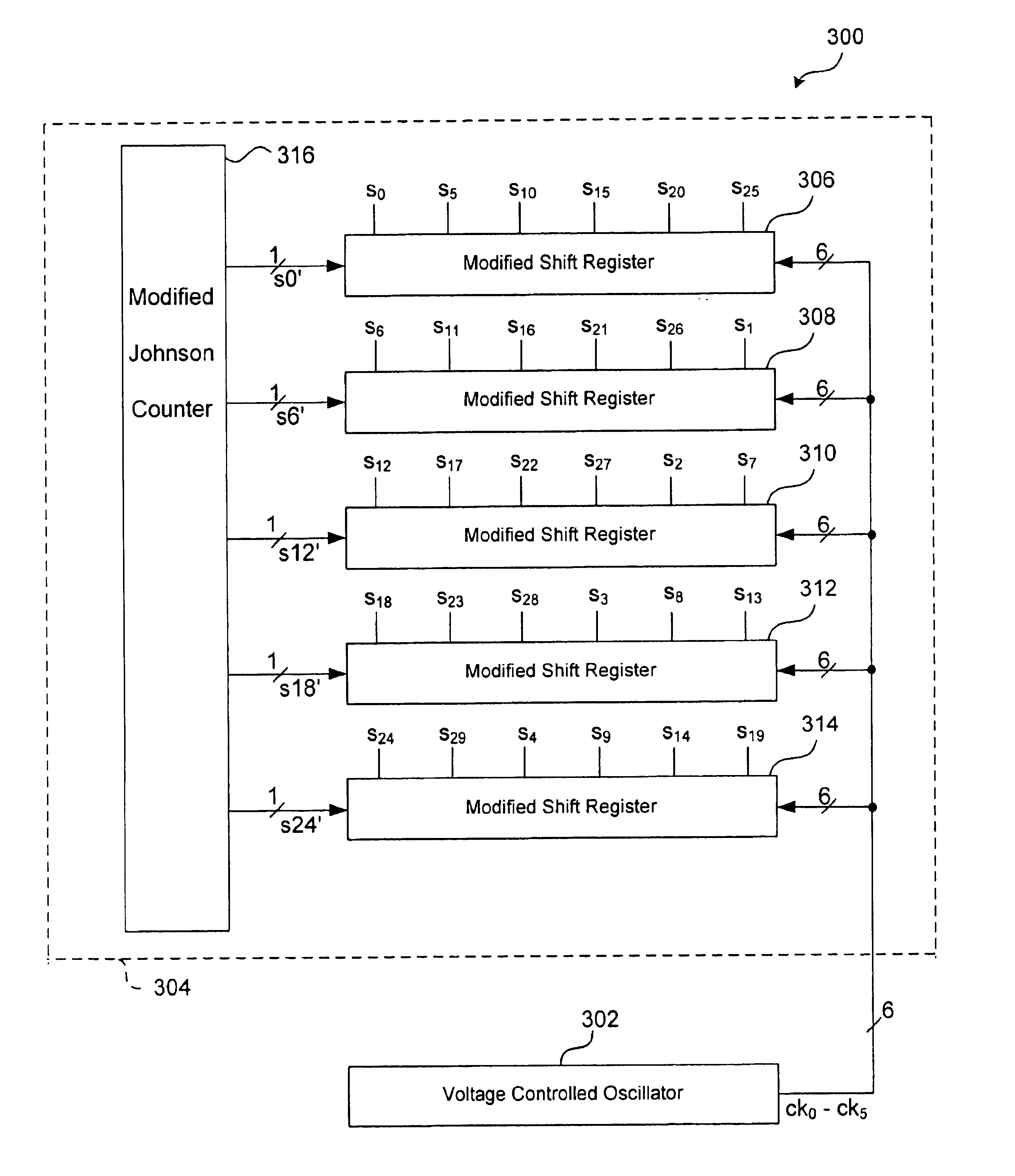
A system and method for multiple-phase clock generation is disclosed. In one embodiment, a multiple-stage voltage controlled oscillator ("VCO") transmits a plurality of clock phases to a clock divider circuit which produces the desired number of clock phase outputs. The clock divider circuit in this embodiment includes a state machine, e.g., a modified Johnson counter, that provides a plurality of divided down clock phases, each of which is connected to a separate modified shift register. Each modified shift register contains D-type flip-flops and each D-type flip-flop provides a separate clock phase output. In one embodiment the number of clock phase outputs of the multiple-phase clock is a function of the number of VCO clock phases times the number of desired states in the modified Johnson counter.

Description

1. Technical FieldThis invention relates to systems and methods for multiple-phase clock generation.2. Description of the BackgroundDigital circuitry is being used in applications requiring seemingly ever faster processing speeds. For example, complementary metal oxide semiconductor ("CMOS") devices have been used to sample high-frequency carrier-modulated signals in order to recover the data in such signals, often as part of a communications device. Because the frequency of the signals is sometimes far in excess of the speeds capable of any individual CMOS device, the signals are oversampled by arrays of similar sampling circuitry clocked by multiple-phase ("multi-phase") clocks in order to simulate a single much faster device. Oversampling of such high-speed signals makes it possible to use comparatively slow CMOS devices for high-speed applications such as communications and computing by using multiple-phase clocks to process high-speed signals in parallel. Correspondingly, as th...

Claims


Application Information

Patent Timeline
IPC IPC(8): G06F1/06H03K5/15H03K23/00H03K23/54H03L7/099H03L7/08H03L7/089
CPCG06F1/06H03K5/15013H03L7/0995H03K23/542H03L7/0891H03K5/15
Inventor KIM, OOKLI, HUNG SUNGLEE, INYEOLKIM, GYUDONGLEE, YONGMAN
Owner UNIVERSAL CONNECTIVITY TECH INC
Learn More