Optical communication module

a communication module and optical communication technology, applied in the field of optical communication modules, can solve the problems of difficult to make the light from the incident ld incident on the optical transmitting medium, and achieve the effects of reducing signal distortion, reducing stray capacitance and parasitic inductance, and reducing signal distortion

Inactive Publication Date: 2005-01-04
SUMITOMO ELECTRIC IND LTD
View PDF12 Cites 17 Cited by
  • Summary
  • Abstract
  • Description
  • Claims
  • Application Information

AI Technical Summary

Benefits of technology

[0033]It is possible to mount an LD driving element on the second substrate. This is because the MPD is mounted on the inclined surface, and consequently the distance from the LD to the rear part of the MPD is shortened, thereby allowing the LD driving element to be mounted dose to the LD. Mounting of the LD driving element close to the LD produces a short interconnection, thereby

Problems solved by technology

Since the light emitted from the LD is small in diameter and large in spread angle, it

Method used


Image

  • Optical communication module
  • Optical communication module
  • Optical communication module

Examples


seventh embodiment

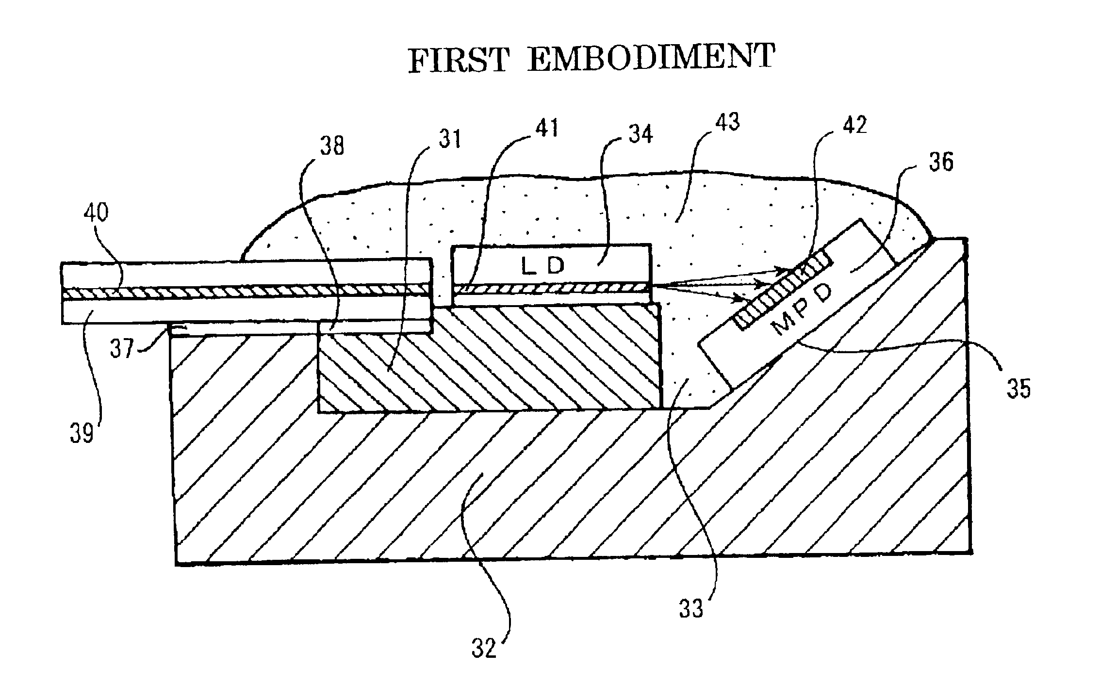
ion module according to the present invention where an optical fiber is used as an optical transmitting medium, and an LD driving IC is mounted in the device.

[0046]FIG. 13 is an axial cross-section view showing an optical communication module according to an eighth embodiment of the present invention where an optical waveguide is used as an optical transmitting medium.

[0047]FIG. 14 is a diagram showing the calculated results of the coupling efficiency between the MPD and the LD which generate horizontal polarized light (S-wave), for the case without an anti-reflection coating and the case with an anti-reflection coating, with an inclined angle α set to 0 to 90 degrees, under the conditions: the wavelength of the LD is 1.3 μm; the light receiving diameter of the MPD is 200 μm; the distance between the rear end of the LD and the central point of the PD surface is 400 μm; the refractive index of the MPD is 3.5; the refractive index of the transparent resin is 1.46; and the refractive i...


PUM


Abstract

An optical communication module, such as an optical transmitter used for optical communication incorporating a semiconductor laser (LD) and a monitoring photodiode (MPD), and an optical transceiver including a photodiode (PD), is efficiently and inexpensively provided. As means therefor, two substrates are used, that is, an expensive and high-accuracy first substrate is accommodated in an recess provided in a second substrate that is inexpensive and that needs less accuracy. An optical transmission system is mounted on the first substrate, and the MPD is mounted on the second substrate having an inclined surface provided on an opposite side of the recess in terms of the optical transmission direction. This eases production work and simultaneously allows the decreaseed use of expensive substrates.

Description

TECHNICAL FIELD[0002]The present invention relates to an optical communication module incorporating a semiconductor laser diode and a monitoring photodiode used for optical communication. More particularly, the present invention relates to an optical transmitter that has been reduced in size and cost by simply arranging the monitoring photodiode, or relates to an optical communication module including the same. The optical transmitter refers to a module combining a semiconductor laser (Laser Diode; LD) generating transmitting signals and a monitoring photodiode (Monitoring Photodiode; MPD) monitoring the output thereof. Since the semiconductor laser varies in the current and optical output characteristic due to secular changes thereof, it is necessary to monitor the intensity of light and to maintain the optical output power constant. For this purpose, a module using an LD is frequently equipped with an MPD.[0003]The optical transceiver (LP / PD Module) refers to one combining such an...

Claims


Application Information

Patent Timeline
IPC IPC(8): G02B6/42H01S5/022H01S5/00G02B6/36H01S5/042H01S5/0232
CPCG02B6/42G02B6/4201G02B6/421H01S5/02284G02B6/423G02B6/4202H01S5/0683H01S5/02216H01S5/02228H01S5/02252H01L2224/48091H01L2224/45144H01S5/02234H01S5/02326H01S5/0231H01S5/02251H01S5/0232H01L2924/00014H01L2924/00
Inventor NAKANISHI, HIROMIKUHARA, YOSHIKIOKADA, TAKESHI
Owner SUMITOMO ELECTRIC IND LTD
Why Eureka
Try Eureka