Phase shifted test pattern for monitoring focus and aberrations in optical projection systems

a phase shift and test pattern technology, applied in the field of testing and characterization of lenses, can solve the problems of inability to use pmi in the field to measure lens aberration, and inability to meet the requirements of standard production operations

Inactive Publication Date: 2005-01-11
GLOBALFOUNDRIES INC
View PDF5 Cites 36 Cited by
  • Summary
  • Abstract
  • Description
  • Claims
  • Application Information

AI Technical Summary

Benefits of technology

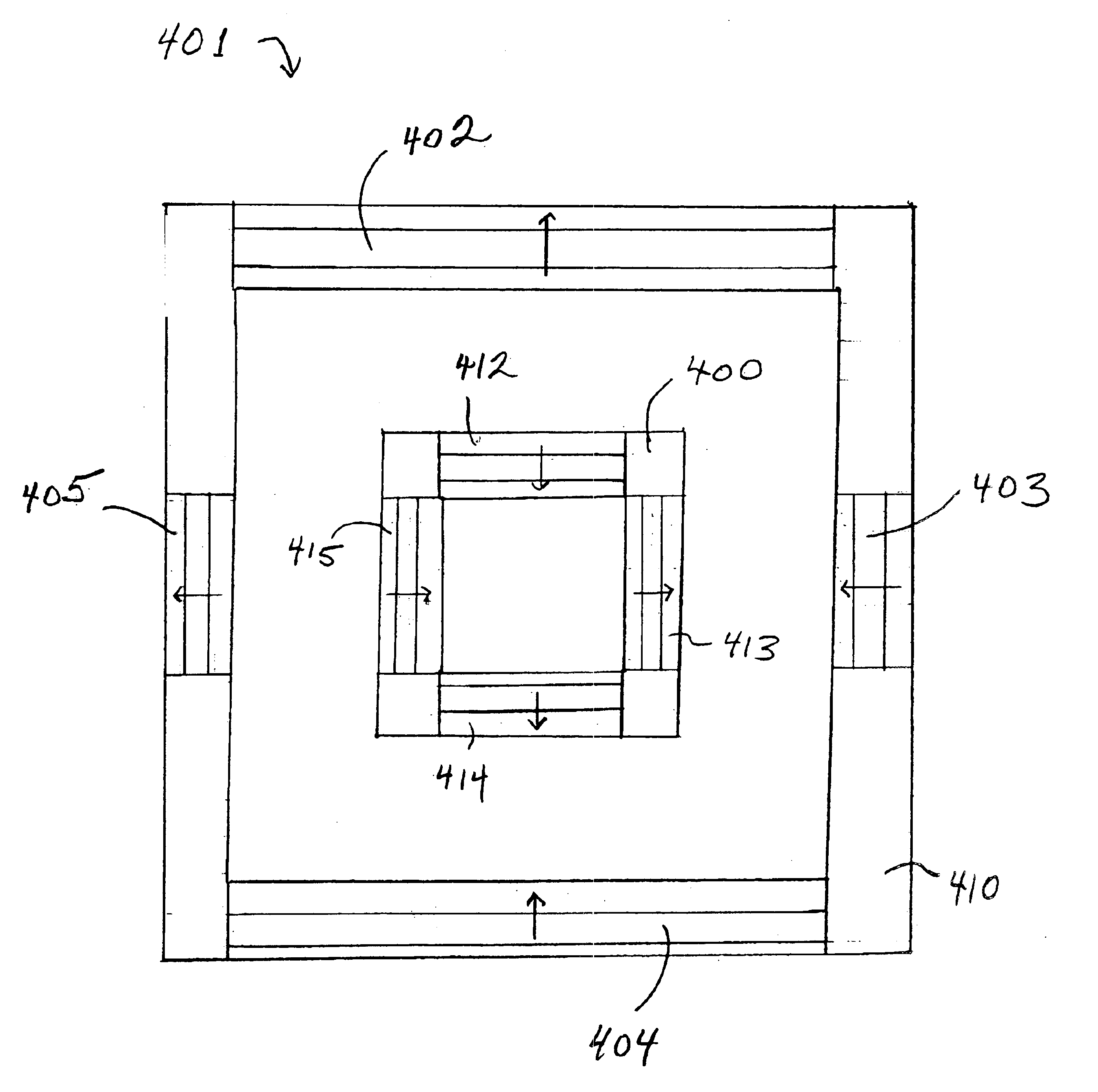
The blazed gratings of the present invention are preferably formed to diffract a single beam. The test patterns used with in accordance with the present invention are preferably in the form of standard overlay metrology test patterns, such as box-in-box patterns, although the invention is not limited to the use of box-

Problems solved by technology

However, after the optical system is complete, it is very difficult and uncommon to use PMI in the field to measure lens aberration.
Additionally, lens aberrations may change over time, so that the corrections for lens aberrations measured during manufacturing become obsolete.
However, SEM measurements are not

Method used


Image

  • Phase shifted test pattern for monitoring focus and aberrations in optical projection systems
  • Phase shifted test pattern for monitoring focus and aberrations in optical projection systems
  • Phase shifted test pattern for monitoring focus and aberrations in optical projection systems

Examples


Embodiment Construction

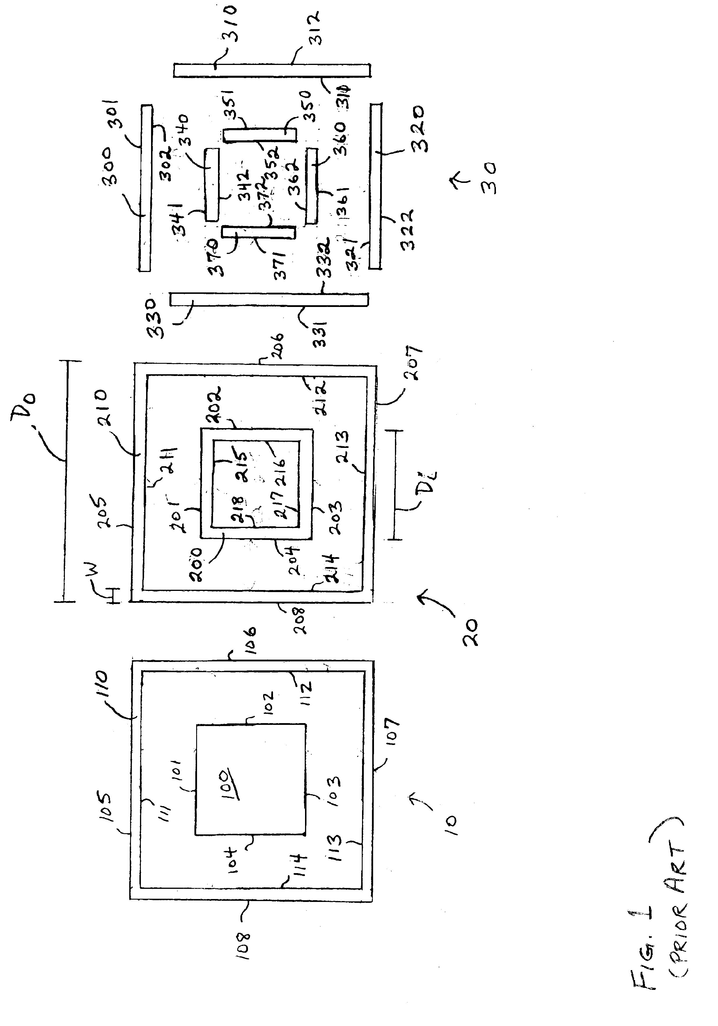
In the following descriptions of the preferred embodiments of the invention, a method is described for measuring lens aberrations using test patterns designed in accordance with the invention to be using in conjunction with standard metrology equipment. It will be appreciated that this is intended as an example only, and that the invention may be practiced under a variety of conditions and using a variety of layouts and design constraints.

In production lithography, it is standard practice to ensure overlay registration of each level deposited on a wafer by measuring the positioning of a test pattern on a resist layer relative to a test pattern printed on the underlying layer. Test patterns are also used to measure other lithographic parameters such as bias in the printed critical dimensions. Tools to perform overlay measurement and other metrology measurements are standard equipment in production lithography. Many test patterns for performing overlay alignment measurements or and ot...


PUM


Abstract

A method is described for determining lens aberrations using a test reticle and a standard metrology tool. The method provides test patterns, preferably in the form of standard overlay metrology test patterns, that include blazed gratings having orientation and pitch selected to sample desired portions of the lens pupil. The method measures relative shifts in the imaged test patterns using standard metrology tools to provide both magnitude and sign of the aberrations. The metrology tools need not be modified if standard test patterns are used, but can be adapted to obtain additional information. The test reticles may be formed with multiple test patterns having a range of orientations and pitch in order to compute any desired order of lens aberration. Alternatively, single test patterns may be used to determine both the magnitude and sign of lower order lens aberrations, such as defocus or coma.

Description

FIELD OF THE INVENTIONThe present invention generally relates to testing and characterization of lenses and, more particularly, to the quantitative measurement of aberrations in lithographic lenses.BACKGROUND OF THE INVENTIONIn various high performance optical imaging systems, A very large scale integrated (VLSI) complementary metal oxide semiconductor (CMOS) chip is manufactured on a silicon wafer by a sequence of material additions (i.e., low pressure chemical vapor depositions, sputtering operations, etc.), material removals (i.e., wet etches, reactive ion etches, etc.), and material modifications (i.e., oxidations, ion implants, etc.). These physical and chemical operations interact with the entire wafer. For example, if a wafer is placed into an acid bath, the entire surface of the wafer will be etched away. In order to build very small electrically active devices on the wafer, the impact of these operations has to be confined to small, well defined regions.Lithography in the c...

Claims


Application Information

Patent Timeline
IPC IPC(8): G01M11/02G03F1/14
CPCG01M11/0264
Inventor AUSSCHNITT, CHRISTOPHER P.BRUNNER, TIMOTHY A.KIRK, JOSEPH P.SEONG, NAKGEUON
Owner GLOBALFOUNDRIES INC
Why Eureka
Try Eureka