Organic anti-reflective coating compositions for advanced microlithography

a technology of anti-reflective coating and microlithography, which is applied in the direction of photosensitive materials, instruments, photomechanical equipment, etc., can solve the problems of reducing the image quality of the processed photoresist, and reducing the resolution of the photoresis

Inactive Publication Date: 2005-01-25
BREWER SCI
View PDF9 Cites 30 Cited by
  • Summary
  • Abstract
  • Description
  • Claims
  • Application Information

AI Technical Summary

Benefits of technology

It will be appreciated that this invention provides a distinct advantage in that the use of an additional crosslinking agent is not necessary. That is, the polymer provides the necessary crosslinking in and of itself. Thus, in this embodiment, the anti-reflective coating compositions are essentially free (i.e., less than about 0.01% by weight) of any added crosslinking agents.

Problems solved by technology

However, a frequent problem encountered by photoresists during the manufacturing of semiconductor devices is that activating radiation is reflected back into the photoresist by the substrate on which it is supported.
Such reflectivity tends to cause blurred patterns which degrade the resolution of the photoresist.
Degradation of the image in the processed photoresist is particularly problematic when the substrate is non-planar and / or highly reflective.
This footing profile is not desirable as it can be transferred to the substrate in pattern transfer plasma etch processes.
This can lead to device failures.
Furthermore, the use of these types of crosslinking agents can affect how the composition planarizes over topography.
Most traditional crosslinking agents result in shrinkage of the anti-reflective coating film upon baking, resulting in voids within the via holes, insufficient coverage on top of the via holes, and / or large thickness variations between isolated and dense vias.

Method used

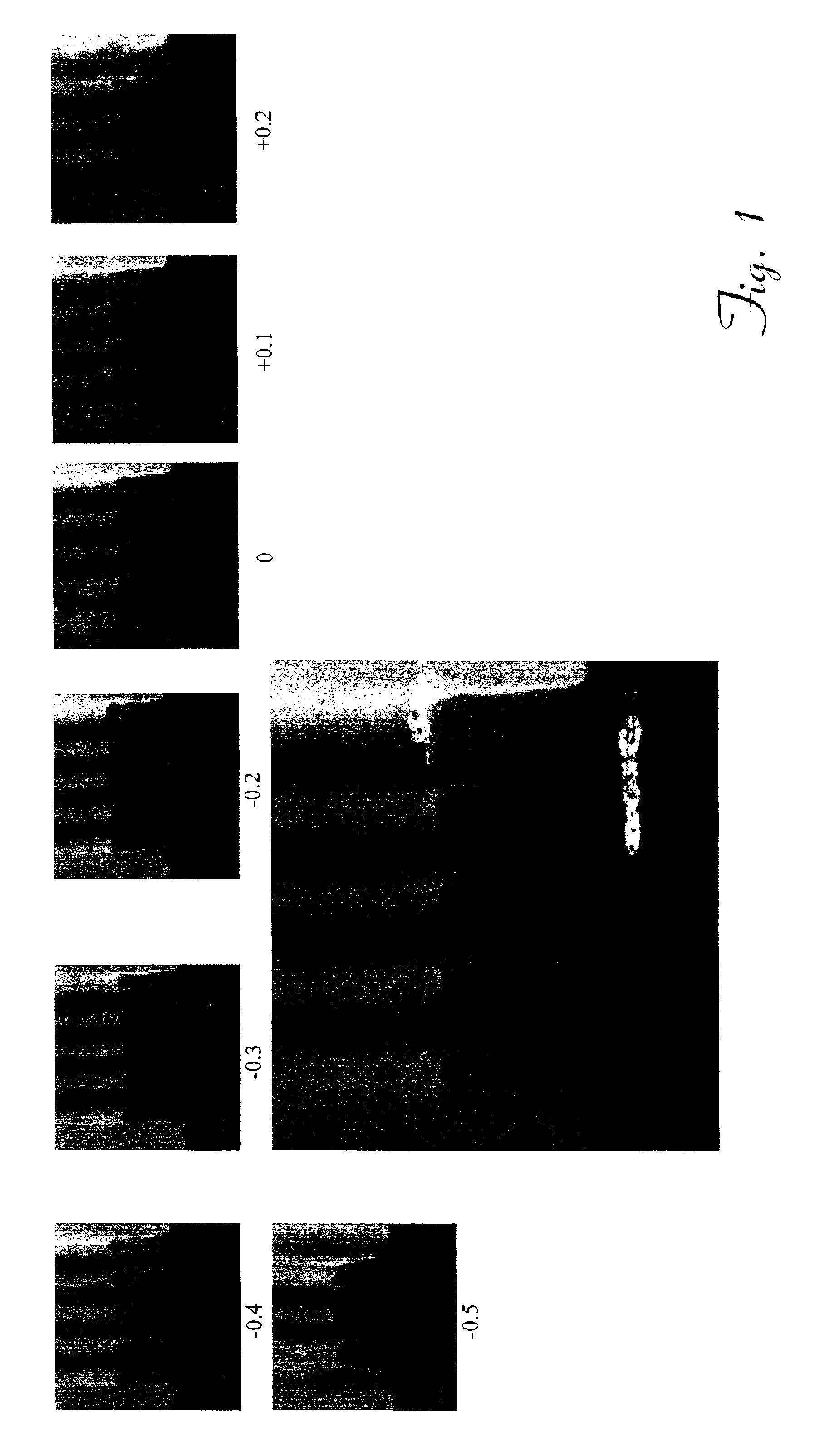
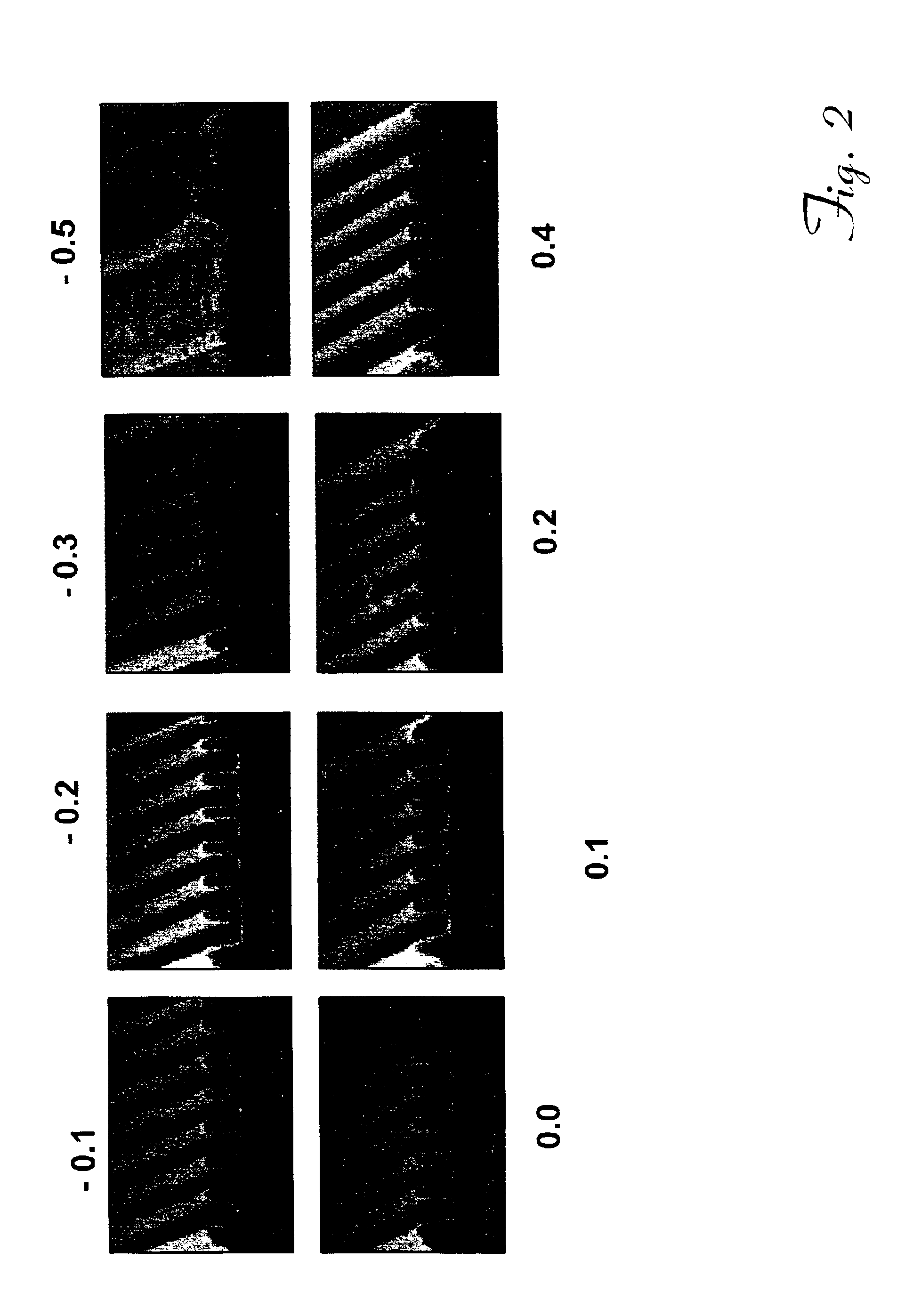
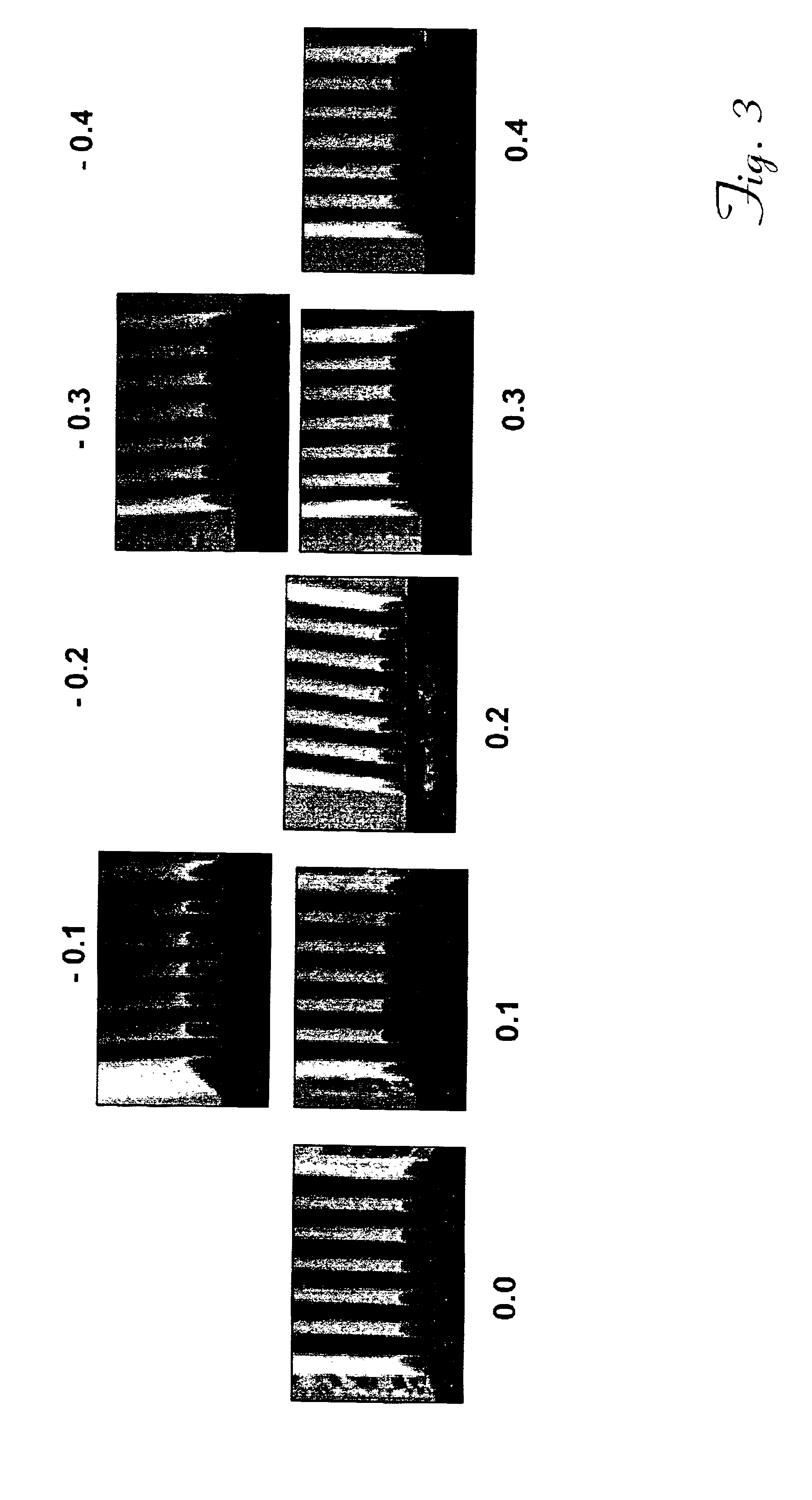

Image

  • Organic anti-reflective coating compositions for advanced microlithography
  • Organic anti-reflective coating compositions for advanced microlithography
  • Organic anti-reflective coating compositions for advanced microlithography

Examples


example 1

1. Anti-reflective Coating without Crosslinking Agent

An epoxy cresol novolac resin (ECN 1299, available from Dow Chemical Company) was dissolved in a 75:25 solvent solution of ethyl lactate:PGMEA to obtain reaction mixture having a solids content of approximately 20% by weight. Equimolar amounts of trimellitic anhydride (obtained from Aldrich Chemical Company) were added to the reaction mixture. Benzyl triethyl ammonium chloride (BTEAC) was added to the mixture (2% by weight, based upon the weight of epoxy cresol novolac resin), and the reaction mixture was heated to 120° C. in an oil bath under a nitrogen atmosphere for two hours. The reaction mixture was then cooled and formulated into an anti-reflective coating (at a solids content of approximately 5% by weight) by the addition of p-toluenesulfonic acid (p-TSA) as the catalyst for crosslinking at a temperature of 205° C. Tables 1 and 2 set forth the respective formulations of the mother liquor and anti-reflective coating composit...

example 2

1. Anti-reflective Coating with a Trivinylether Crosslinking Agent

An epoxy cresol novolac resin (ECN 1299) was dissolved in a 75:25 solvent solution of ethyl lactate:PGMEA to obtain a reaction mixture having a solids content of approximately 20% by weight. Equimolar amounts of 4-hydroxybenzoic acid were added to the reaction mixture. BTEAC was added to the mixture (2% by weight, based upon the weight of epoxy cresol novolac resin), and the reaction mixture was heated to 120° C. in an oil bath under a nitrogen atmosphere for twenty-four hours. The reaction mixture was cooled and formulated into an anti-reflective coating (at a solids content of approximately 5% by weight) by the addition of trimethylolpropane trivinylether (crosslinking agent, obtained from Aldrich Chemical Company) and p-TSA as the catalyst for crosslinking at a temperature of 205° C. Tables 5 and 6 set forth the respective formulations of the mother liquor and anti-reflective coating compositions.

TABLE 5Mother Liqu...


PUM

PropertyMeasurementUnit
molecular weightaaaaaaaaaa
temperatureaaaaaaaaaa
compositionaaaaaaaaaa

Abstract

New polymers and new anti-reflective compositions containing such polymers are provided. The compositions comprise a polymer (e.g., epoxy cresol novolac resins) bonded with a chromophore (4-hydroxybenzoic acid, trimellitic anhydride). The inventive compositions can be applied to substrates (e.g., silicon wafers) to form anti-reflective coating layers having high etch rates which minimize or prevent reflection during subsequent photoresist exposure and developing.

Description

BACKGROUND OF THE INVENTION1. Field of the InventionThe present invention is concerned with new polymers, new anti-reflective compositions containing such polymers and methods of using these new anti-reflective compositions to manufacture microelectronic devices. These compositions include a polymer formed from a starting polymer (e.g., epoxy cresol novolac resins) grafted with a chromophore (e.g., trimellitic anhydride, 4-hydroxybenzoic acid).2. Description of the Prior ArtIntegrated circuit manufacturers are consistently seeking to maximize substrate wafer sizes and minimize device feature dimensions in order to improve yield, reduce unit case, and increase on-chip computing power. Device feature sizes on silicon or other chips are now submicron in size with the advent of advanced deep ultraviolet (DUV) microlithographic processes.However, a frequent problem encountered by photoresists during the manufacturing of semiconductor devices is that activating radiation is reflected back...

Claims


Application Information

Patent Timeline
Patent Type & Authority Patents(United States)
IPC IPC(8): C08F8/00C08G63/00C08G59/42C08F8/14C08G63/68C08G59/62C08G65/329C08G65/00C08G63/91C08G59/14C09D171/00C09D163/00C09D167/00C08G59/00C09D171/02G03F7/09C08G59/32C09D133/02
CPCC08F8/14C08G59/1438C08G59/32C08G59/42C08G59/625C08G63/68C08G65/329C09D133/02C09D163/00C09D167/00C09D171/02G03F7/091C08G63/91Y10S430/106G03F7/0045H01L21/027
Inventor DESHPANDE, SHREERAM V.
Owner BREWER SCI
Why Eureka
Try Eureka