Zero IF complex quadrature frequency discriminator and FM demodulator

Inactive Publication Date: 2005-01-25
ARRIS ENTERPRISES LLC
View PDF1 Cites 24 Cited by
  • Summary
  • Abstract
  • Description
  • Claims
  • Application Information

AI Technical Summary

Benefits of technology

It is another objective of the present invention to provide an FD, which, in combination with an XOR phase detector

Problems solved by technology

The multiplied noise will then phase modulate the voltage controlled oscillator (VCO) and will significantly degrade and limit its phase noise performance.
This noise multiplication is often the key factor causing degradation of phase noise performance in synthesizers.
During acquisition of the phase lock, the phase detector (PD) alone may not be able to provide an adequate steering signal necessary for locking, and additional means for assisting the frequency acquisition is often necessary.
The frequency discriminators of the prior art used in frequency synthesizers are inherently limited in speed.
The relatively long propagation delays and settling times of the flip-flops limit the maximum speed (or frequency) of the FD operation, and thus indirectly limits the maximum comparison frequency in a PLL employing such an FD.
The limitations of these flip-flop based circuits are mainly related to speed (i.e. to the maximum operating frequency).
Their physical limitations are the set-up and hold times of the flip flops, the propagation delays from their Clock, Reset and D inputs to the outputs, as well as the usual propagation delays of the combinatorial logic and their interconnections.
Those limitations produce two types of artifacts associated particularly with the phase-detection, namely the “dead-zone” and the “blind-spot”.
Another disadvantage of performing phase detection using one of those PFDs is that they are quite noisy, and require a charge pump with a relatively narrow low-pass filter (or integrator) because the phase correction pulses to the charge pump may occur at very low frequencies.
Another disadvantage of the prior art FDs is that t

Method used


Image

  • Zero IF complex quadrature frequency discriminator and FM demodulator
  • Zero IF complex quadrature frequency discriminator and FM demodulator
  • Zero IF complex quadrature frequency discriminator and FM demodulator

Examples


Example

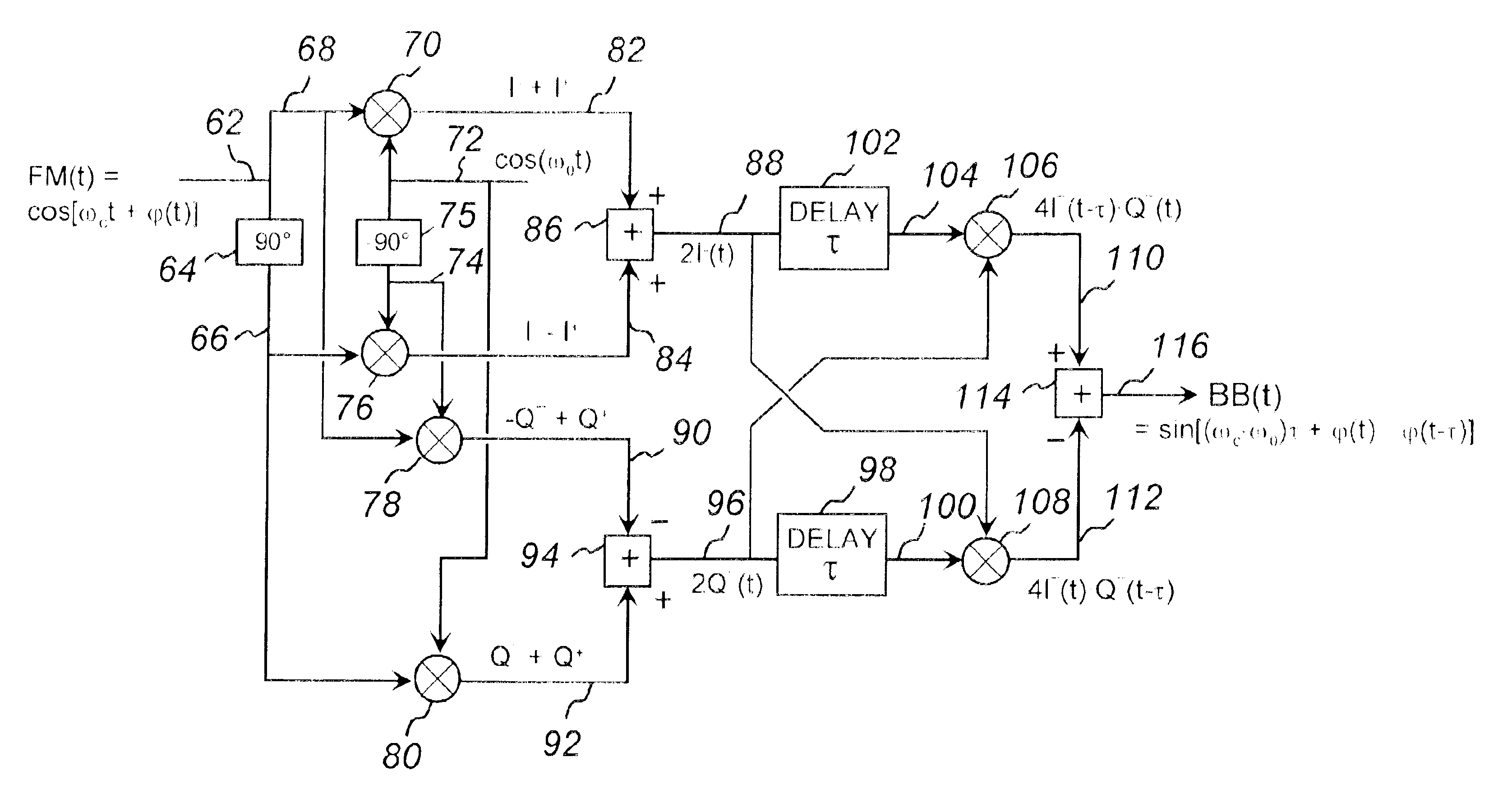
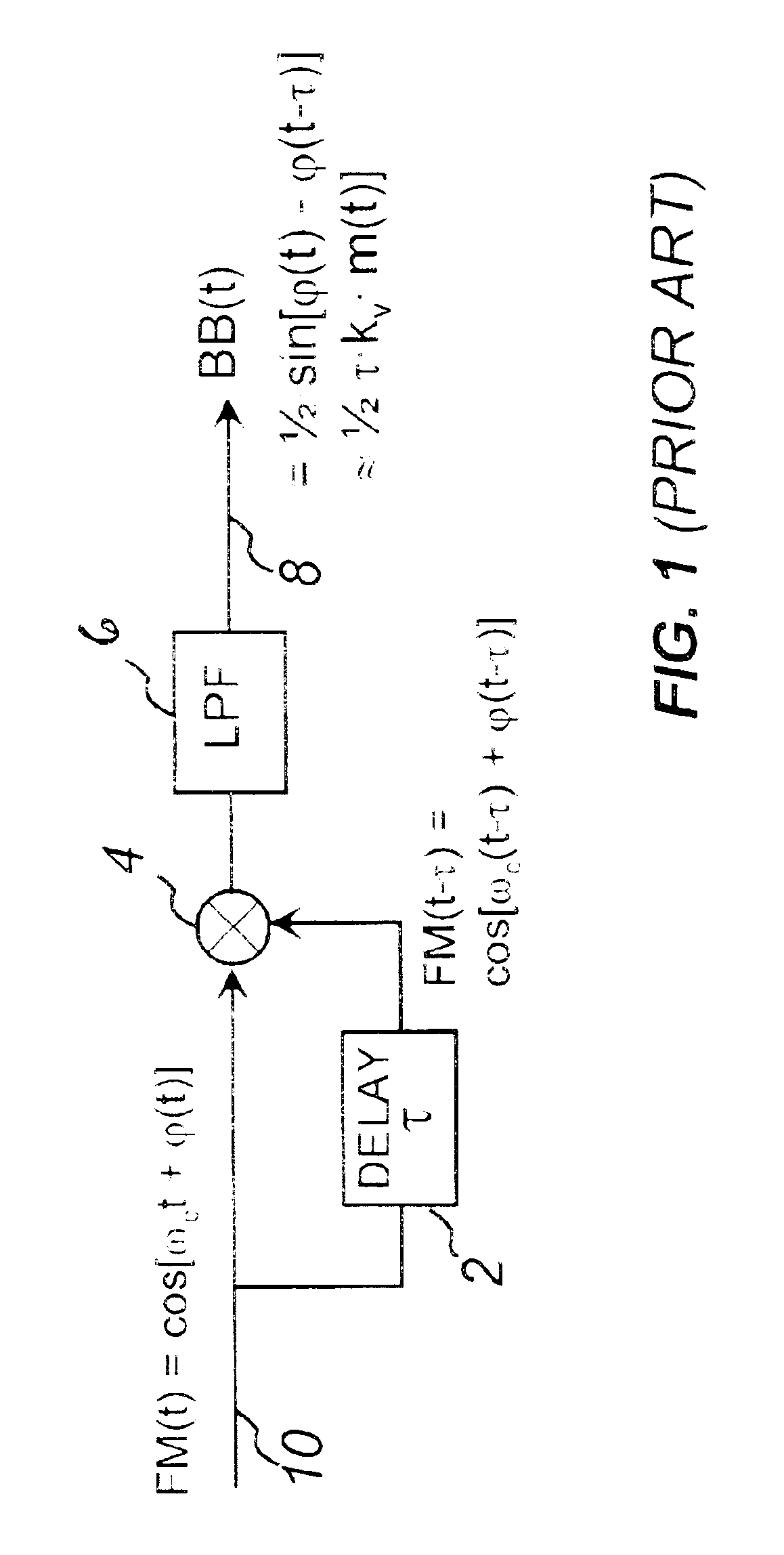
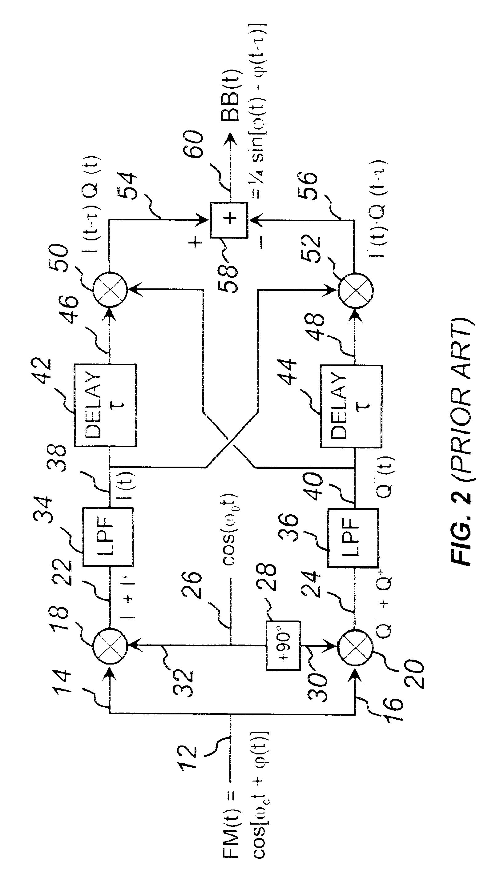
To overcome the problem encountered in the prior art in FIG. 2 of having to filter with low pass filters both the I and Q arms, a complex single side-band (SSB) down-conversion to zero IF using in-phase (I) and quadrature signal (Q) shifted by 90° can be used, as shown in one embodiment of the demodulator of the present invention in FIG. 3. The SSB mixing (also known as image rejection mixing) of two frequencies produces only one dominant frequency, equal to either the sum or the difference of the two frequencies, depending upon which sideband (upper or lower) is produced, which in turn is the function of the phasing of the quadrature components of the two frequencies. The complex SSB down-converter used in the present invention utilizes two sets of SSB mixers—one to produce the in-phase LSB signal, and the other to produce the quadrature LSB signal.

For complex SSB mixing, quadrature signals (0° and 90° phase signals) of both FM and LO signals are required. To obtain the phase shift...


PUM


Abstract

A frequency discriminators (FD) and frequency modulation (FM) demodulators, utilizing single sideband (SSB) complex conversion directly to zero IF, suitable for direct demodulation at high frequencies of analog FM or digital FSK modulated signals, as well as for high speed frequency discrimination (or frequency comparison) in applications such as frequency acquisition in frequency synthesizers. The complex SSB down-converter consists of a quad of mixers and quadrature splitters in both the signal path and local oscillator (LO) path. Each mixer receives both the signal and the LO, each either in-phase or quadrature. The outputs of mixers are combined in pairs, to produce the SSB in-phase (I) baseband signal and the SSB quadrature (Q) baseband signal. Both I and Q signals are then delayed, each multiplied by un-delayed version of the other one. The multiplication products are summed together, to produce an FD error signal, or an FM demodulated signal at the output. The delay time can be dynamically controlled, in order to set the FD frequency range or to adjust the gain of the FM demodulator.

Description

BACKGROUND OF THE INVENTION1. Field of the InventionThis invention relates to frequency discriminators (FD) and frequency modulation (FM) demodulators, utilizing single sideband (SSB) complex conversion directly to zero intermediate frequency (IF), suitable for direct demodulation at high frequencies of analog FM or digital frequency shift keying (FSK) modulated signals, as well as for high speed frequency discrimination (or frequency comparison) in applications such as frequency acquisition in frequency synthesizers, operating at very high frequencies (in the order of 200 MHz, but not limited to), and especially to their use for frequency acquisition in low phase noise Rational Frequency Synthesizers (disclosed in related and commonly assigned U.S. patent application Ser. No. 09 / 580,513) thus offering significant performance improvements for advantageous applications such as cable television (CATV), high speed digital communications (digital TV and high speed cable data modems for ...

Claims


Application Information

Patent Timeline
IPC IPC(8): H03D3/00
CPCH03D3/007
Inventor PETROVIC, BRANISLAV A.ASHKENASI, MAXIM
Owner ARRIS ENTERPRISES LLC
Why Eureka
Try Eureka