Method for melting or refining glasses or glass ceramics

a technology of glass ceramics and glass ware, which is applied in the direction of glass shaping apparatus, lighting and heating apparatus, furnace components, etc., can solve the problems of inability to heat the melt surface special, lack of high long-term stability and high breaking strength, and refractory material

Inactive Publication Date: 2005-02-01
SCHOTT AG
View PDF14 Cites 9 Cited by
  • Summary
  • Abstract
  • Description
  • Claims
  • Application Information

AI Technical Summary

Benefits of technology

Another important advantage of the invention is the swelling point that occurs in the channel. The glass is forced to flow upward by the HF energy input and the temperature increase in the center that is associated therewith forces the flow upward. In this way, the refining bubbles successfully reach the melt surface. In classical tubs, such an upward flow is forced primarily by one wall in the refining region, so that the glass flow is directed upward. This wall can be omitted in the case of the HF-heated channel. Here, there is a “natural flow”, which provides for this effect. Simulation calculations have shown in fact that the flow swelling point in the skull channel is basically more effective for refining than the classically utilized wall. In addition to the improved refining, it is also advantageous, of course, that abrasion of a wall cannot occur.
is the swelling point that occurs in the channel. The glass is forced to flow upward by the HF energy input and the temperature increase in the center that is associated therewith forces the flow upward. In this way, the refining bubbles successfully reach the melt surface. In classical tubs, such an upward flow is forced primarily by one wall in the refining region, so that the glass flow is directed upward. This wall can be omitted in the case of the HF-heated channel. Here, there is a “natural flow”, which provides for this effect. Simulation calculations have shown in fact that the flow swelling point in the skull channel is basically more effective for refining than the classically utilized wall. In addition to the improved refining, it is also advantageous, of course, that abrasion of a wall cannot occur.
It is excellently suitable for continuous operation. It can thus operate very economically.
Due to the configuration and arrangement of the induction coils in the lying-down position, the channel is open at the top. The level of the melt is exposed. The surface of the melt is thus freely accessible for the installation of an additional heating device, for example, a gas burner or an electrical heating device. This top heating is of particular advantage for the case when the channel is utilized as a refining aggregate. High surface temperatures can be obtained accordingly, so that the bursting of bubbles is assured in the region of the surface.
The heating from above is also helpful if high-frequency energy failure occurs. In this way, at least the glass transport can be assured. Also, the melt temperature can be maintained at such a value that a recoupling is possible when high-frequency heating is again started up.
Further, there is no danger of condensation of products of evaporation on the water-cooled coil pipes, since these are not found above the level of the melt.

Problems solved by technology

However, it can also consist of refractory material.
However, it does not have a high long-term stability and a high breaking strength.
In addition, a special heating of the melt surface is not possible.
In fact, a certain cooling occurs, which can lead to the formation of a tough skin in the surface region.
The channel therefore cannot be used for refining.
If the channel is used for melting, and the melt contains readily volatile components, then there is a risk of condensation at the cooled superstructure of the channel.
The condensate can thus drip into the melt in an uncontrolled manner.
This can lead to glass defects in the form of nodes, blisters or streaks.
If corrosion of the coil material occurs, then this leads to discoloration of the glass, depending on the material of the coil.
This is not acceptable, particularly in the case of optical glasses.
Further, there are very many optical glasses, which have a high proportion of fluorine, phosphate or other highly aggressive components.
The corrosion can be strong enough that discharge of cooling water occurs, so that the operational safety of the plant is no longer assured.
A high corrosion and an increase in spectral extinction associated therewith are unavoidable.

Method used


Image

  • Method for melting or refining glasses or glass ceramics
  • Method for melting or refining glasses or glass ceramics
  • Method for melting or refining glasses or glass ceramics

Examples


Embodiment Construction

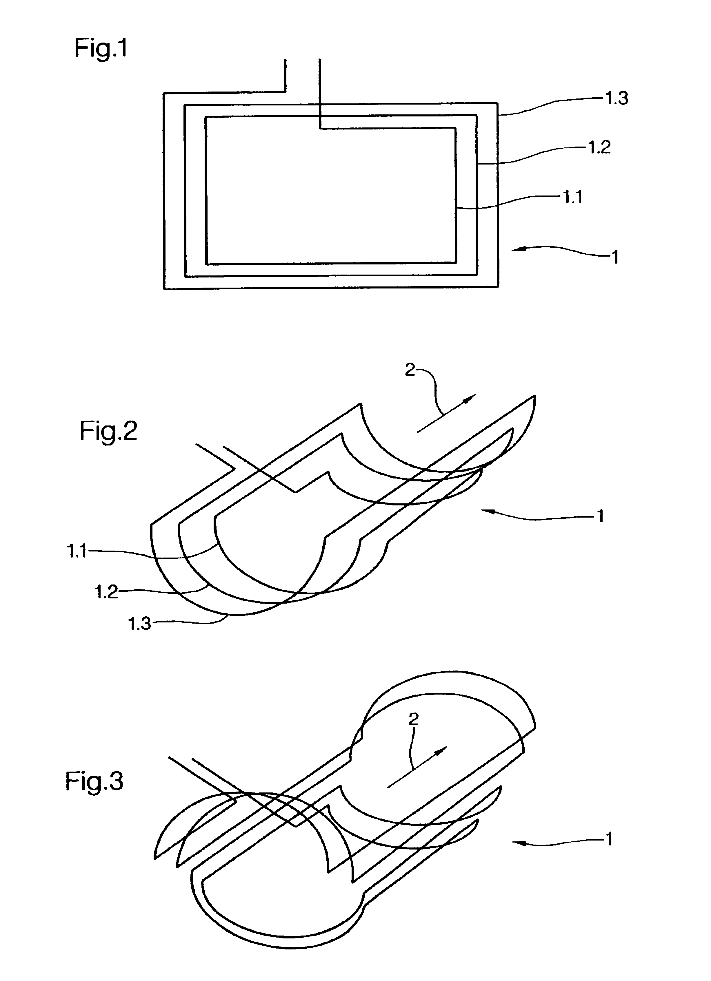
Coil 1 shown in FIG. 1 has endless-screw-shaped running windings 1.1, 1.2, 1.3. In the present case, the windings lie in a horizontal plane, precisely in the direction of glass flow 2. The inside diameter of the inner winding in the direction of glass flow 2 is relatively large. It can amount to a multiple of the inside diameter perpendicular to the direction of glass flow 2.

The coil 1 shown in FIG. 2 is also shaped like an endless screw and has windings 1.1, 1.2, 1.3. It is understood that a much larger number of windings is also possible. This coil is slightly curved in a plane. The winding segments running in the direction of glass flow 2 lie on both sides of the channel, which is not shown 1D here.

The windings are subdivided in the coil shown in FIG. 3. Winding segments are again recognized, which run in a straight line parallel to the direction of glass flow. The curved winding segments lie at the beginning and the end of the channel. One-half of the windings run below and one-...


PUM

PropertyMeasurementUnit
Energyaaaaaaaaaa

Abstract

This invention relates to a device for melting or refining glass or glass ceramics. According to the invention, such a device is provided with the following characteristics: a channel which is arranged in an essentially horizontal manner and which is provided with an inlet and an outlet for the glass melt; and an HF coil for coupling HF energy into the melt is allocated to the channel. The channel is made of a plurality of metal pipes in a similar way to a skull pot. Said pipes can be connected to a cooling medium.

Description

FIELD OF THE INVENTIONThe invention concerns a device for the refining of glasses or glass ceramics.BACKGROUND OF THE INVENTIONSuch devices have become known in the configuration of the so-called “skull pot”. They comprise a pot walling. This is generally cylindrical. It is constructed of a crown of vertical metal pipes. Slots remain between adjacent pipes. The bottom of the pot can also be constructed of metal pipes. However, it can also consist of refractory material. The ends are connected to vertical pipes for the introduction of cooling agent or for the discharge of cooling agent.Heating is conducted by means of an induction coil, which surrounds the pot walling and by means of which high-frequency energy can be input into the contents of the pot.Such a skull pot has been made known from DE 3,316,546 C1.A skull pot operates as follows: The pot is filled with a fresh glass batch or refuse glass or a mixture thereof. The glass or the melt must first be preheated in order to obtai...

Claims


Application Information

Patent Timeline
IPC IPC(8): C03B5/00C03B5/02H05B6/30C03B5/225C03B5/235C03B5/44C03B7/07
CPCC03B5/021
Inventor KOLBERG, UWEROMER, HILDEGARDLENTES, FRANK-THOMASWEIDMANN, GUNTER
Owner SCHOTT AG
Why Eureka
Try Eureka