Long lifetime polymer light-emitting devices with improved luminous efficiency and improved radiance

a polymer and light-emitting diode technology, applied in the direction of thermoelectric device junction materials, semiconductor devices, electrical apparatus, etc., can solve the problems of unresolved problems, work functions, unacceptably short device lifetimes, etc., and achieve high work functions, high reflectivity, and high work efficiency

Inactive Publication Date: 2005-02-01
DUPONT DISPLAY +1
View PDF25 Cites 54 Cited by
  • Summary
  • Abstract
  • Description
  • Claims
  • Application Information

AI Technical Summary

Benefits of technology

The present invention relates to a light-emitting diode including an anode that includes a semi-transparent layer having a high reflectivity and a high work function, and a cathode including at least...

Problems solved by technology

Alkali metals tend to be too mobile and act to dope the emissive layer (e.g., electroluminescent polymer), thereby causing shorts and unacceptably short device lifetimes. Alloys of these low work function metals, for example, alloys of magnesium in silver and alloys of lithium in aluminum, are also known (see, for example, VanSlyke, U.S. Pat. No. 5,047,687; VanSlyke, S. A., Tang, C. W., U.S. Pat. No. 5,...

Method used


Image

  • Long lifetime polymer light-emitting devices with improved luminous efficiency and improved radiance
  • Long lifetime polymer light-emitting devices with improved luminous efficiency and improved radiance
  • Long lifetime polymer light-emitting devices with improved luminous efficiency and improved radiance

Examples


examples

The following examples illustrate certain features and advantages of the present invention. They are intended to be illustrative of the invention, but not limiting.

In the Examples and Comparative Examples below, the following procedure was followed to determine the following measurements:

Efficiency:

Efficiencies were measured using a UDT S370 optometer (available from UDT, a part of Gamma Scientific, of San Diego, Calif.) which includes a photodiode that is calibrated using the procedure described below: The photodiode is calibrated as follows: A NIST calibrated light source, with a known, uniform light emission was used. A mask was used so that only a light beam the size of the pixel active area was emitted. The photodiode was placed at a given distance from the light, and the number of volts were recorded. Thus, the number of volts corresponding to a particular light intensity (340 cd / m2) were known.

Radiance:

Radiance was measured using a Newport photodiode (available from Newport C...

example 1

A polymer LED device was fabricated as in Comparative Example A, except that the ITO was replaced with a vapor deposited layer of silver at a thickness of 300 Å.

example 2

A polymer LED device was fabricated as in Comparative Example A, except that a layer of silver at a thickness of 300 Å was vapor deposited on top of the ITO. The performance of this device is similar to that of Example 1 and Example 3, as described below.


PUM


Abstract

The luminous efficiency and radiance of light emitting diodes (LEDs) fabricated from organic emissive materials can be increased by using a multilayer cathode including a low work function layer and a high work function high reflectivity layer, in combination with a high work function, high reflectivitity anode material in the device.

Description

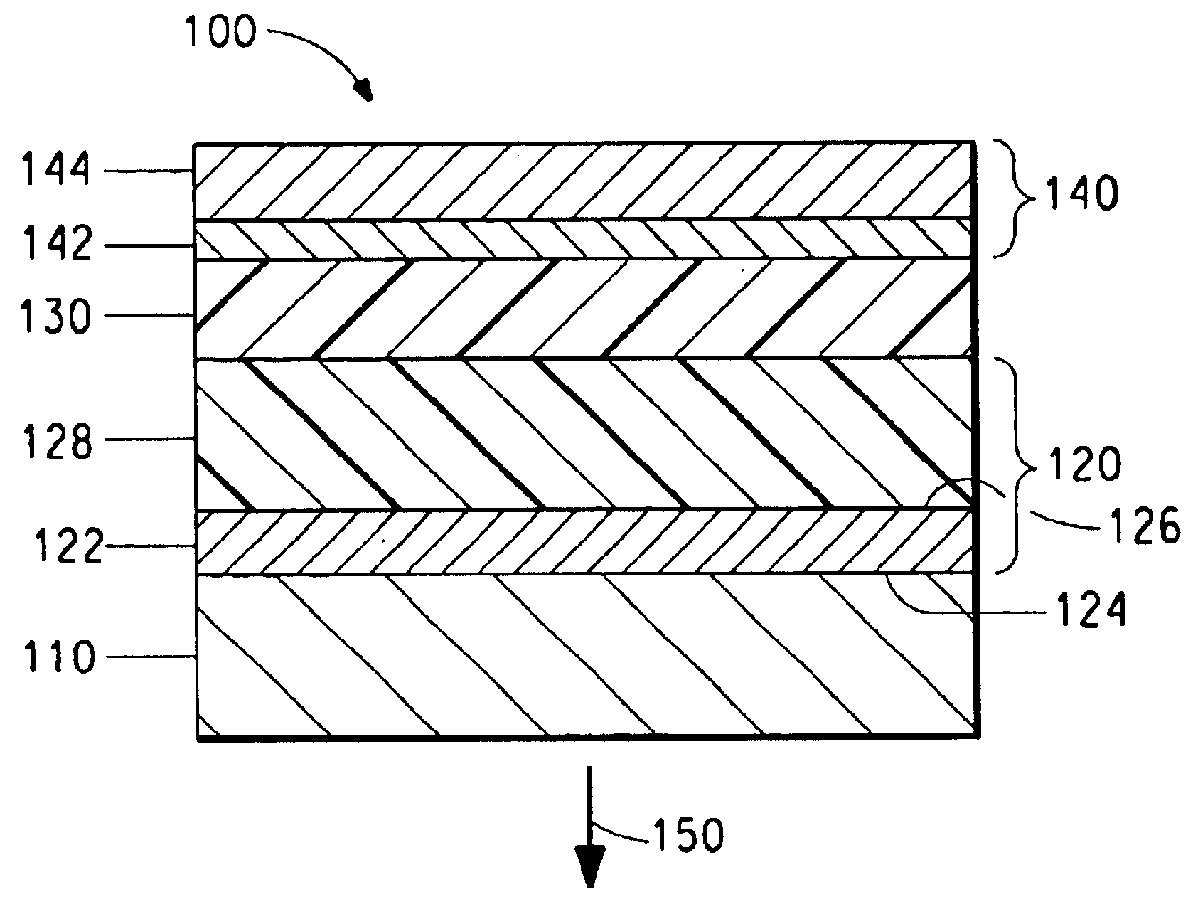
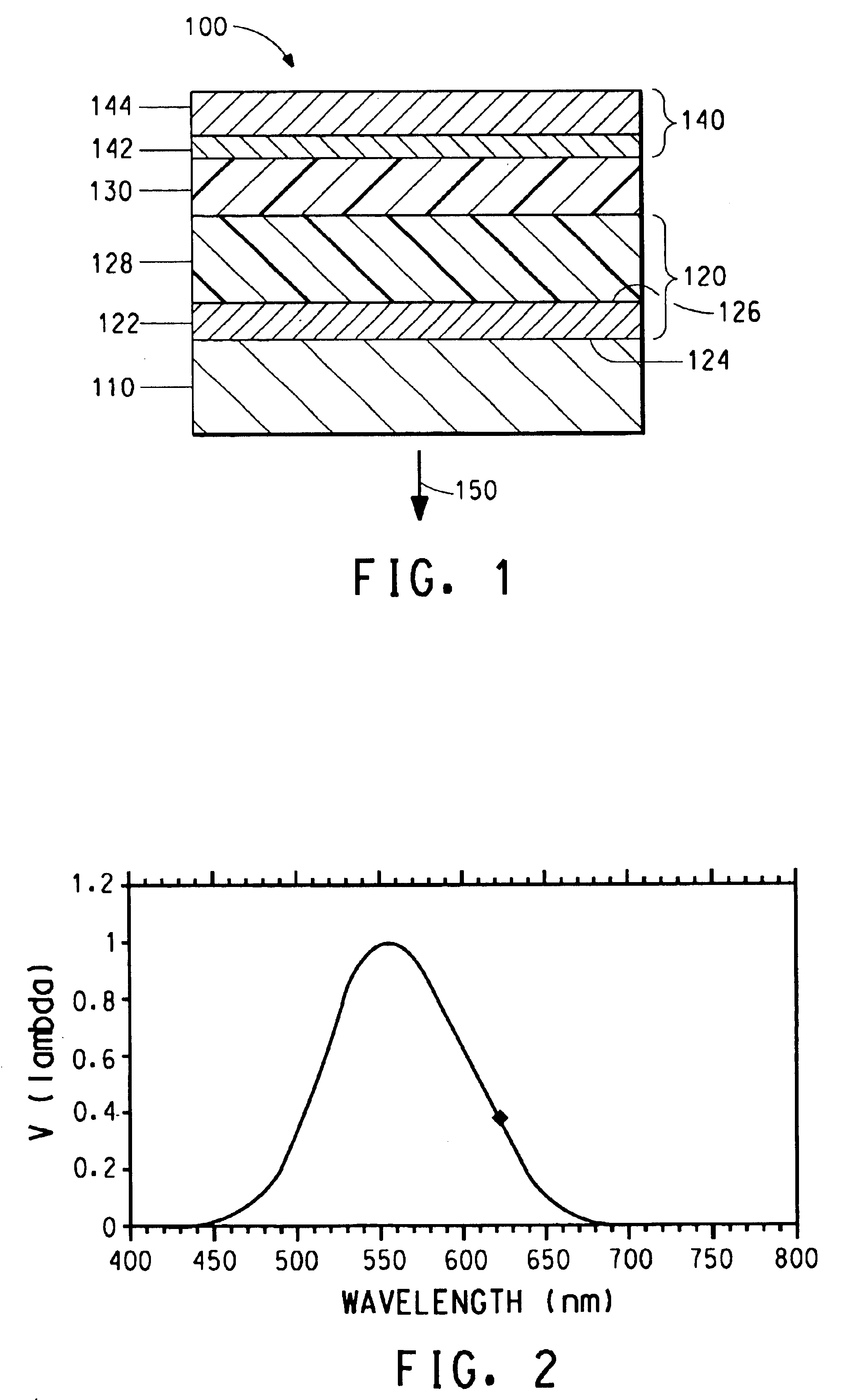
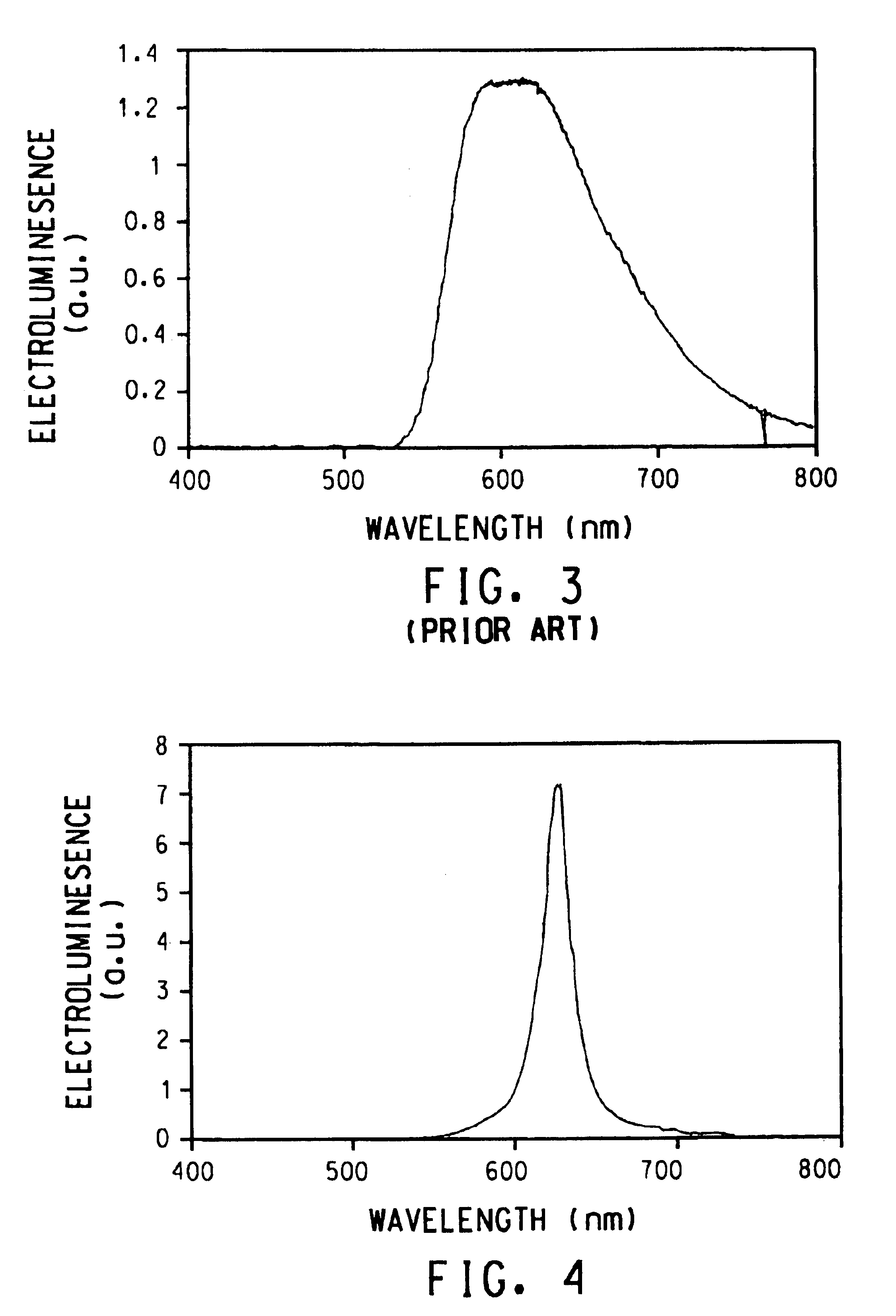
BACKGROUND OF THE INVENTION1. Field of the InventionThis invention relates to organic polymer light-emitting diodes with improved luminous efficiency and improved radiance.2. Description of the Related ArtDiodes and particularly light emitting diodes (LEDs) fabricated with conjugated organic polymer layers have attracted attention due to their potential for use in display technology. A standard polymer LED architecture includes the following layers in contact sequence: a substrate with a coating of indium-tin oxide (ITO), a passivation layer, emissive polymer, followed by a single-layer cathode. [See for example, Burroughs, J. H., Bradley, D. D. C., Brown, A. R., Marks, R. N., Mackay, K., Friend, R. H., Bums, P. L., and Holmes, A. B., “Light-emitting diodes based on conjugated polymers,”Nature, 1990, 347, 539; Braun, D., and Heeger, A. J., “Visible light emission from semiconducting polymer diodes,”Appl. Phys. Lett., 1991, 58, 1982.]In the field of organic polymer-based LEDs, it is ...

Claims


Application Information

Patent Timeline
IPC IPC(8): H01L35/12H01L35/24H01L51/52
CPCH01L51/5265H01L51/5206H01L51/5221H10K50/17H10K50/81H10K50/826H10K50/852
Inventor O'REGAN, MARIE B.ZHANG, CHI
Owner DUPONT DISPLAY
Why Eureka
Try Eureka