Method for removing COS from a stream of hydrocarbon fluid and wash liquid for use in a method of this type
- Summary
- Abstract
- Description
- Claims
- Application Information
AI Technical Summary
Benefits of technology
Problems solved by technology
Method used
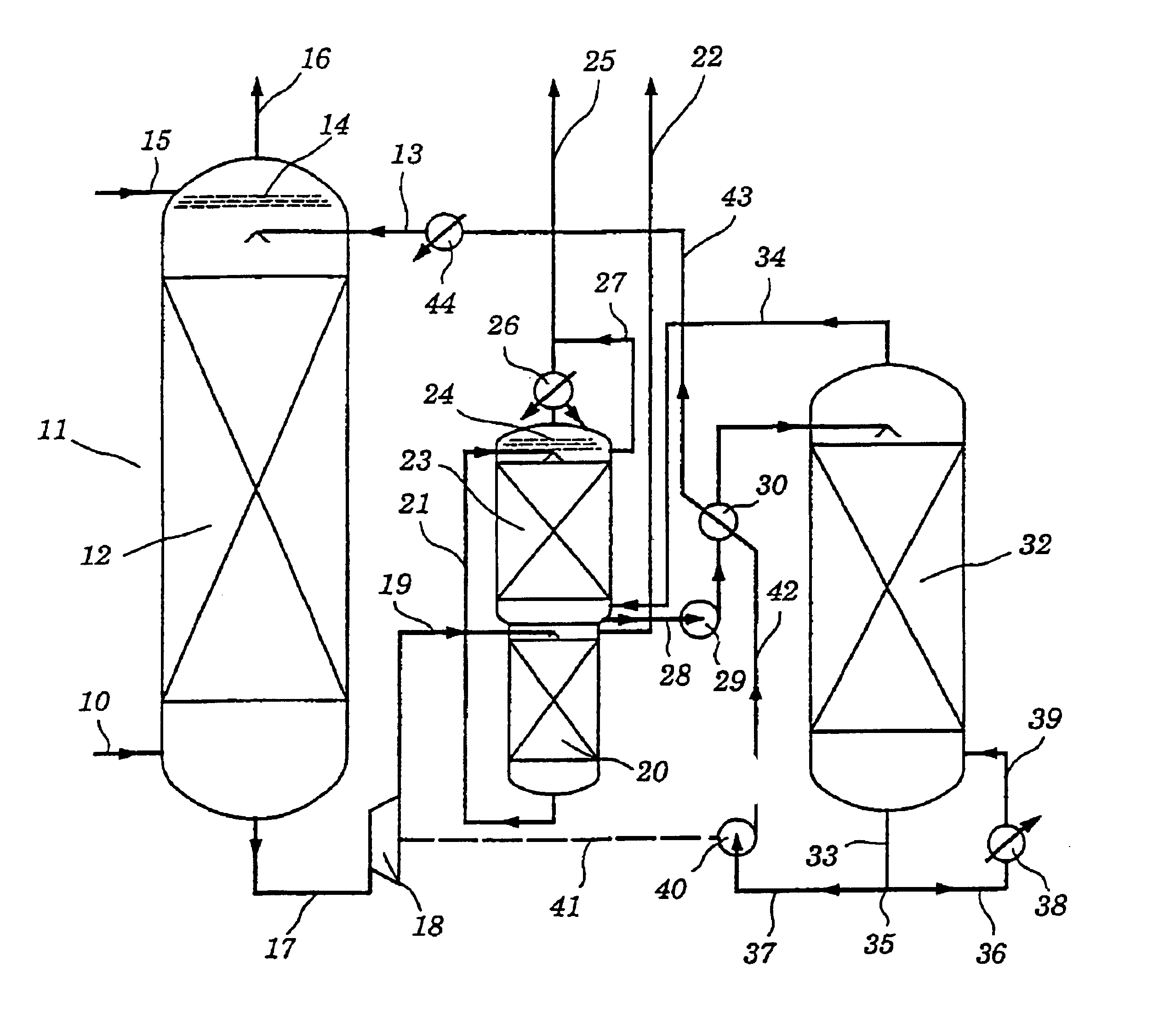
Image

Examples
examples
[0065]The absorption column of an experimental plant was fed with a natural gas composition containing the following impurities: 3 or 8% by volume of CO2, 10% by volume of H2S, from 25 to 150 ppmv of COS, from 120 to 160 ppmv of methyl mercaptan. The operating pressure of the absorber was varied in individual runs, being 40, 54 or 60 bar. The gas and liquid throughputs were calculated as a function of the particular absorber configuration used, the solvent used and the mandated operating parameters to obtain a certain CO2 absorption rate.
[0066]The total amine content of the scrubbing liquor was in each case 40% by weight, based on the total liquor.
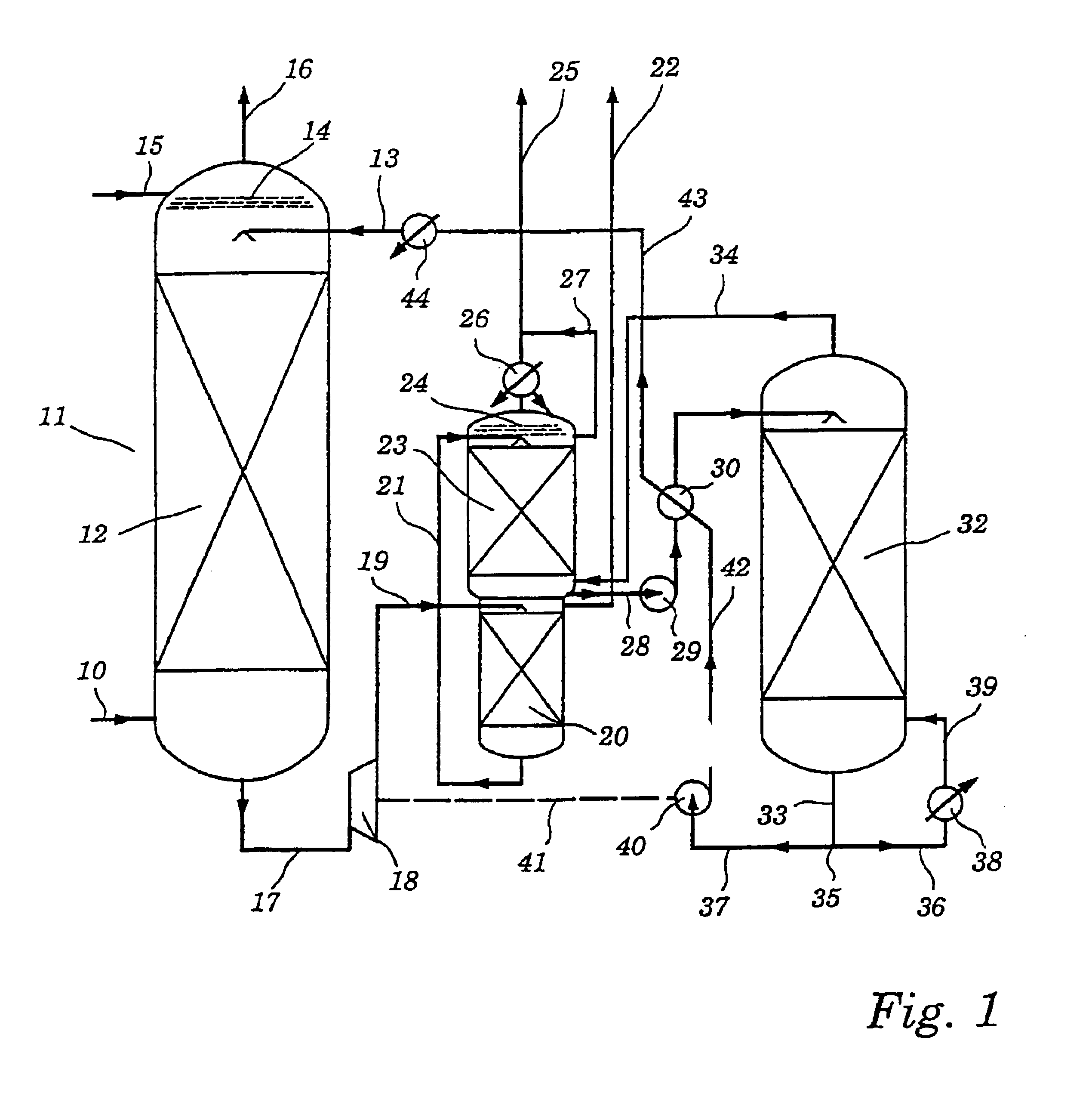
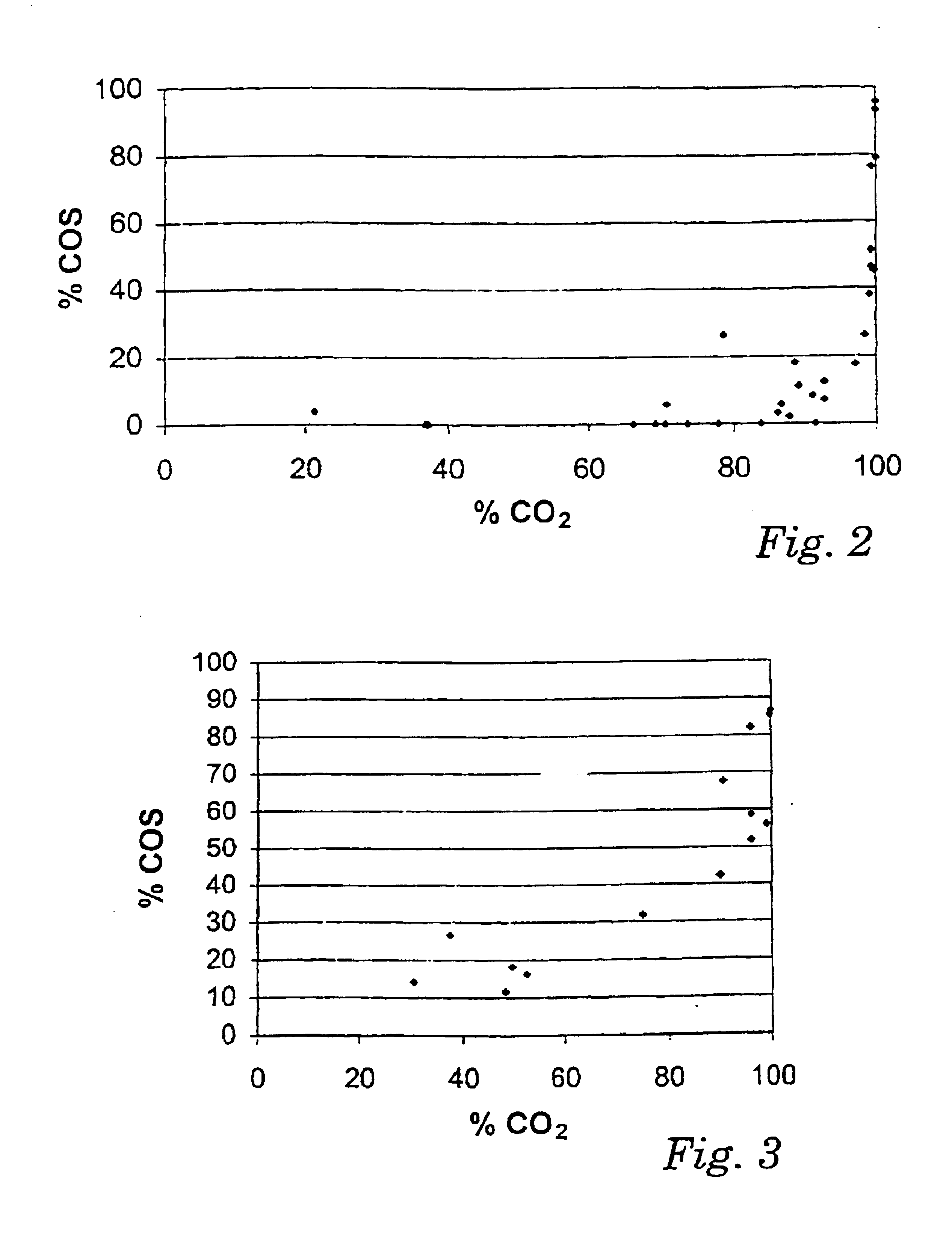
[0067]The diagrams of FIGS. 2 to 5 show the percentage of COS in the gas stream being removed at a certain CO2 absorption rate.
[0068]The diagram of FIG. 2 illustrates the result of a comparative series of runs for a pure MDEA solution having a concentration of about 3.46 mol / l (about 40% by weight) of MDEA.
[0069]It can be seen that up to v...
PUM
| Property | Measurement | Unit |
|---|---|---|
| Temperature | aaaaa | aaaaa |
| Temperature | aaaaa | aaaaa |
| Fraction | aaaaa | aaaaa |
Abstract
Description
Claims
Application Information