Capillary two-phase thermodynamic power conversion cycle system

a two-phase thermodynamic and cycle system technology, applied in the field of two-phase thermodynamic cycle systems, can solve the problems of single rankine power cycle, use of additional power converter, and limited space based dynamic power conversion cycles, etc., and achieve the effect of reducing leakag

Inactive Publication Date: 2005-02-22
THE AEROSPACE CORPORATION
View PDF6 Cites 18 Cited by
  • Summary
  • Abstract
  • Description
  • Claims
  • Application Information

AI Technical Summary

Benefits of technology

For a space-based application, the turbine can have an electromagnetic coupling for eliminating leakage around shaft seals. The superheated vapor drops in pressure as energy is extracted. The flow will then enter the condenser where heat will be transferred out to an external sink in the environment. In practice, the condenser can be a tube that the cycle flow passes through with several serpentine bends. This tube is

Problems solved by technology

Space power systems that generate AC power disadvantageously typically require the use of an additional power converter, such as in photovoltaic systems.
Space based dynamic power conversion cycles have been limited to single-phase Brayton systems, thermoelectrics, and photovoltaics.
Although the Rankine cycle has been used extensively in terrestrial applications for power generation, the Rankine power cycle has not been used in space applications because of the difficulty and complexity required to manage a two-phase power system in micro gravity.
The heating in the boiler of a Rankine cycle system provides the working fluid flow with an infinitesimally small amount of heat input, which results in an infinitesimally smal

Method used


Image

  • Capillary two-phase thermodynamic power conversion cycle system
  • Capillary two-phase thermodynamic power conversion cycle system
  • Capillary two-phase thermodynamic power conversion cycle system

Examples


Embodiment Construction

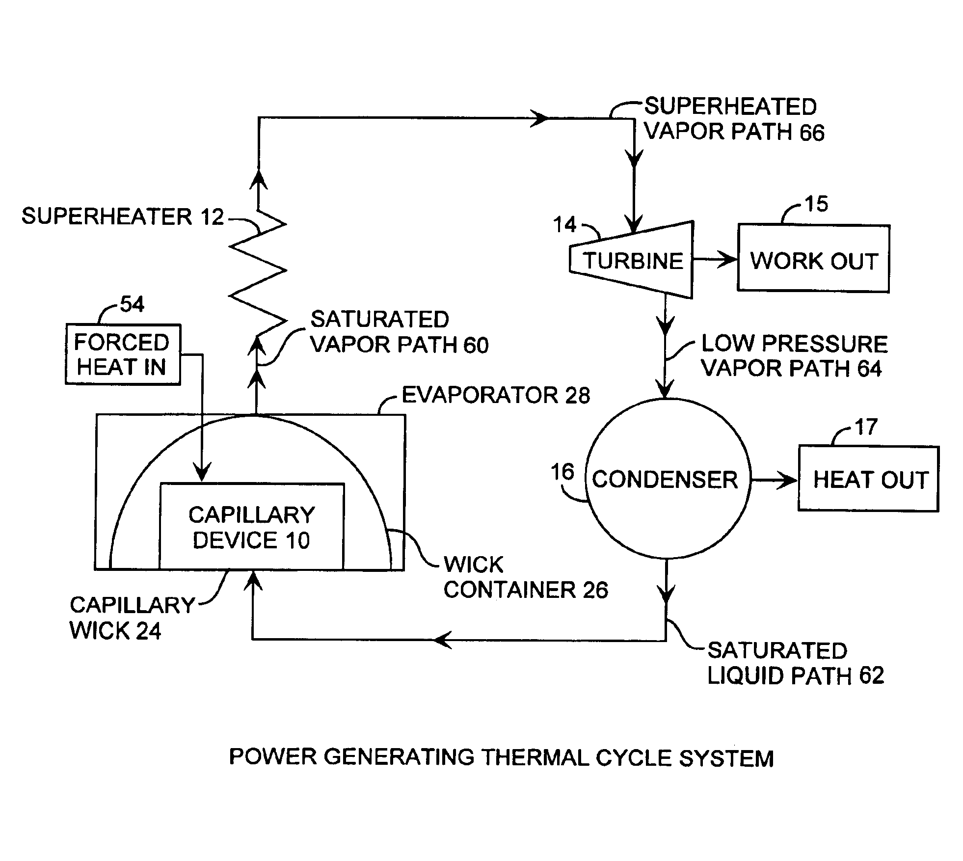
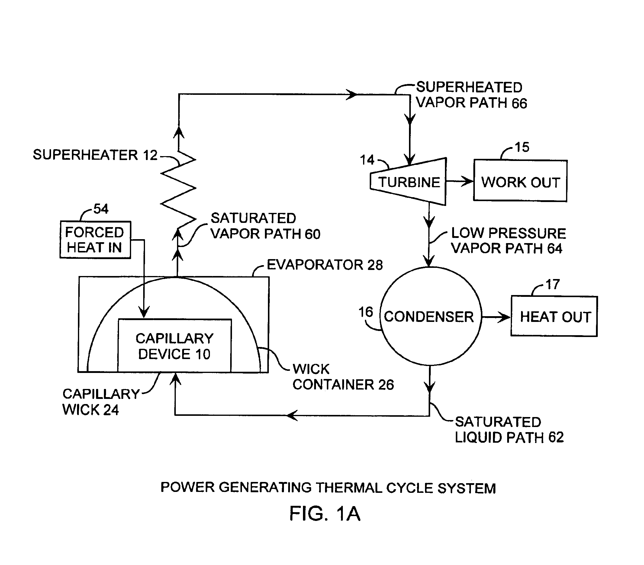
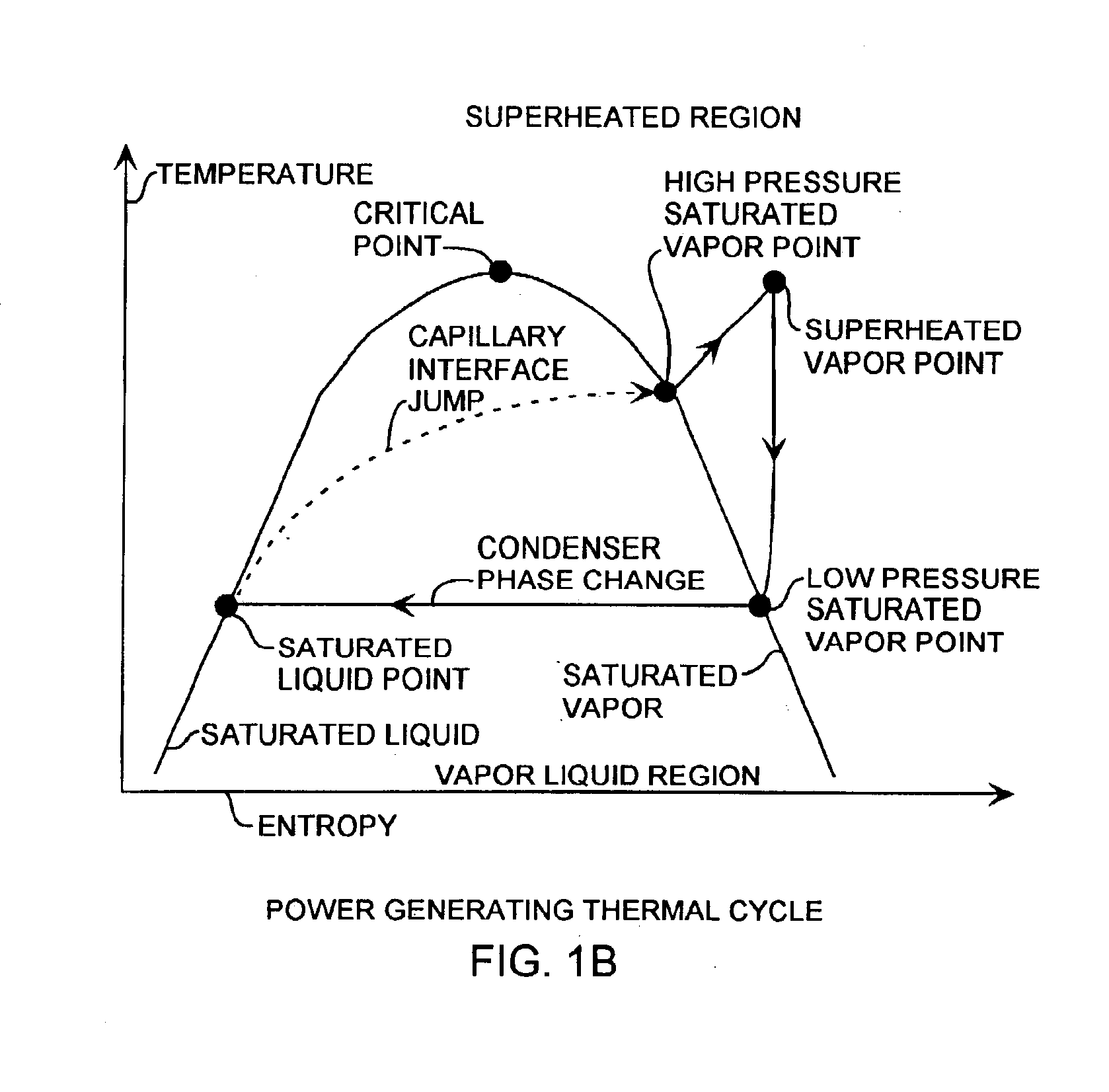
An embodiment of the invention is described with reference to the figures using reference designations as shown in the figures. Referring to FIGS. 1A and 1B, a working fluid, such as amonia or water, obtains a liquid phase and a vapor phase in a two-phase power generation system. The flow starts, for example, as a saturated liquid moving along a saturated liquid path 62 from a condenser 16 to the evaporator 28 of a capillary device 10, comprising a capillary wick 24 within a wick container 26. The evaporator 28, may be, for example, the evaporator from a conventional loop heat pipe or a conventional capillary pumped loop. Forced heat 54 into the capillary device 10 evaporator serves to drive the device. This liquid is pushed to the capillary wick 24 under pressure. The capillary wick 24 provides the separation between the high-pressure saturated vapor and the low-pressure saturated liquid. Flow through the capillary wick 24 is achieved because the working fluid wets the capillary wi...


PUM


Abstract

A two-phase thermodynamic power system includes a capillary device, an inline turbine, and a condenser for generating output power as a generator or receiving input power as a refrigerator. The capillary device, such as a heat loop pipe or a capillary pumped loop, is coupled to the inline turbine for generating output power for power generation or for receiving input power for powered refrigeration. The capillary device receives input heat that is used to change phase of liquid received from the condenser into vapor for driving the turbine. The power system is well suited for space applications using a radioisotope heat source, using waste heat from a radioisotope power system as a heat source, waste heat from spacecraft components such as electronics as a heat source or solar energy as a heat source. The heat source is useful for driving the capillary wick as well as a superheater for increased power efficiency and lifetime operation. The power system is well suited for space receiving heat from a heat source to produce useful mechanical energy. The refrigeration system is well suited for receiving input mechanical power to the turbine for removing waste heat from a spacecraft at a low temperature and rejecting that heat into space at a higher temperature.

Description

FIELD OF THE INVENTIONThe invention relates to the field of thermodynamic power systems. More particularly, the present invention relates to two-phase thermal cycle systems, capillary devices, power generators, thermal condensers, and refrigerators.BACKGROUND OF THE INVENTIONThermodynamic power cycle systems have typically been used to generate useful work, such as in power generation systems, and used for removing heat, such as in refrigeration systems. Thermodynamic power cycles have typically been used in two ways. A first way is to turn heat input into the system into useful work as in power generation systems. A second way is to move heat from a low temperature point to a high temperature point by inputting useful energy as in refrigeration systems. Radioisotope elements are used as a heat source for space power systems. Thermoelectric power conversion systems are currently used in deep space missions. Radioisotope thermoelectric generators have thermodynamic efficiencies of se...

Claims


Application Information

Patent Timeline
IPC IPC(8): B64G1/46B64G1/50F01K15/00F01K15/02F25B41/06
CPCB64G1/506F25B41/067F01K15/02F25B2500/18F25B41/37
Inventor BAKER, KARL WILLIAM
Owner THE AEROSPACE CORPORATION
Why Eureka
Try Eureka