

Tailored zeolite bound zeolite catalysts and its use for hydrocarbon conversion
- Summary
- Abstract
- Description
- Claims
- Application Information
AI Technical Summary
Benefits of technology
Problems solved by technology
Method used
Image

Examples
example 1
Preparation of zeolite bound zeolite. The formation of silica bound ZSM-5 and ZSM-22 extrudates was carried out as follows:
Components UsedQuantityComponentfor Preparation(Grams)No.ZSM-5 crystals12.501ZSM-22 crystals12.502Water6.243Silica Gel (Aerosil300)2.364Silica Sol (Nalcoag24.6651034A)Methocel0.146Water19.527
Components 1 to 6 were mixed in the bowl of a household mixer for 6 minutes. Component 7 was then added to the bowl and mixing continued for 3 more minutes. A thick extrudable paste was obtained. The paste was extruded into 2 mm diameter extrudates. The extrudates were dried 2 hours at room temperature and overnight at 130° C. next, the extrudates were calcined 2 hours at 120° C. (heating rate 0.5° C. / min) and 16 hours at 490° C. (heating rate 1° C. / min).
Composition of calcined silica-bound extrudates:
Zeolite:70 wt. %SiO2 binder:30 wt. %
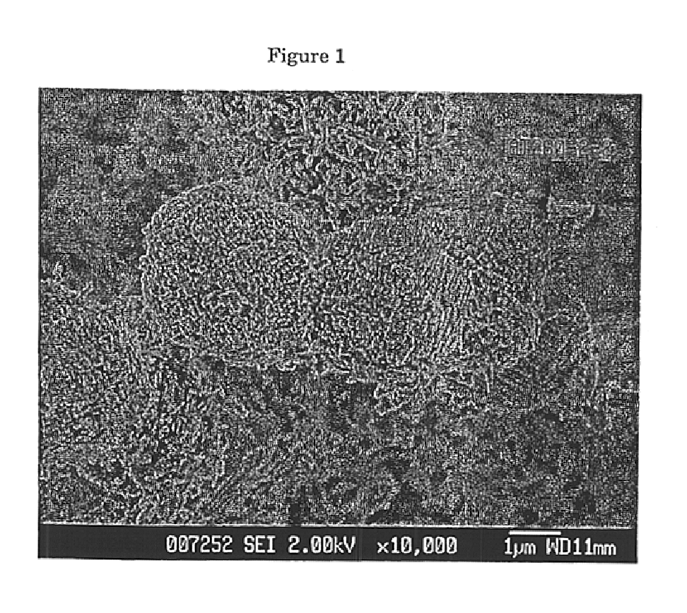
XRD analysis of the green extrudates indicated the presence of both MFI and TON. A halo of amorphous material could be seen which indicated ...
example 2
Preparation of zeolite bound zeolite.
Silica bound ZSM-5 and ZSM-22 extrudates prepared according to Example 1 were converted to the zeolite bound zeolite as follows.
Components UsedQuantityComponentFor Preparation(Grams)No.Silica Bound ZSM-5 / ZSM-5.00122NaOH pellets0.092t-butylammoniumbromide0.773Water9.424
Components 2 and 3 were dissolved in component 4 and stirred until a clear solution was obtained. The template used in the conversion i.e., t-butylammoniumbromide, was specifically chosen to convert the amorphous silica to MEL structure type. Component 1 was then added to the solution. The synthesis mixture was then placed in a stainless steel autoclave at heated at 150° C. for 20 hours (heat up time was 2 hours). The molar composition of the synthesis mixture was:
0.47 Na2O / 0.95 TBABr / 10 SiO2 / 209.5 H2O
The extrudates were washed 5 times in 300 ml water until the conductivity of the last washing water was less then 10 μS / cm and then dried overnight at 120° C.
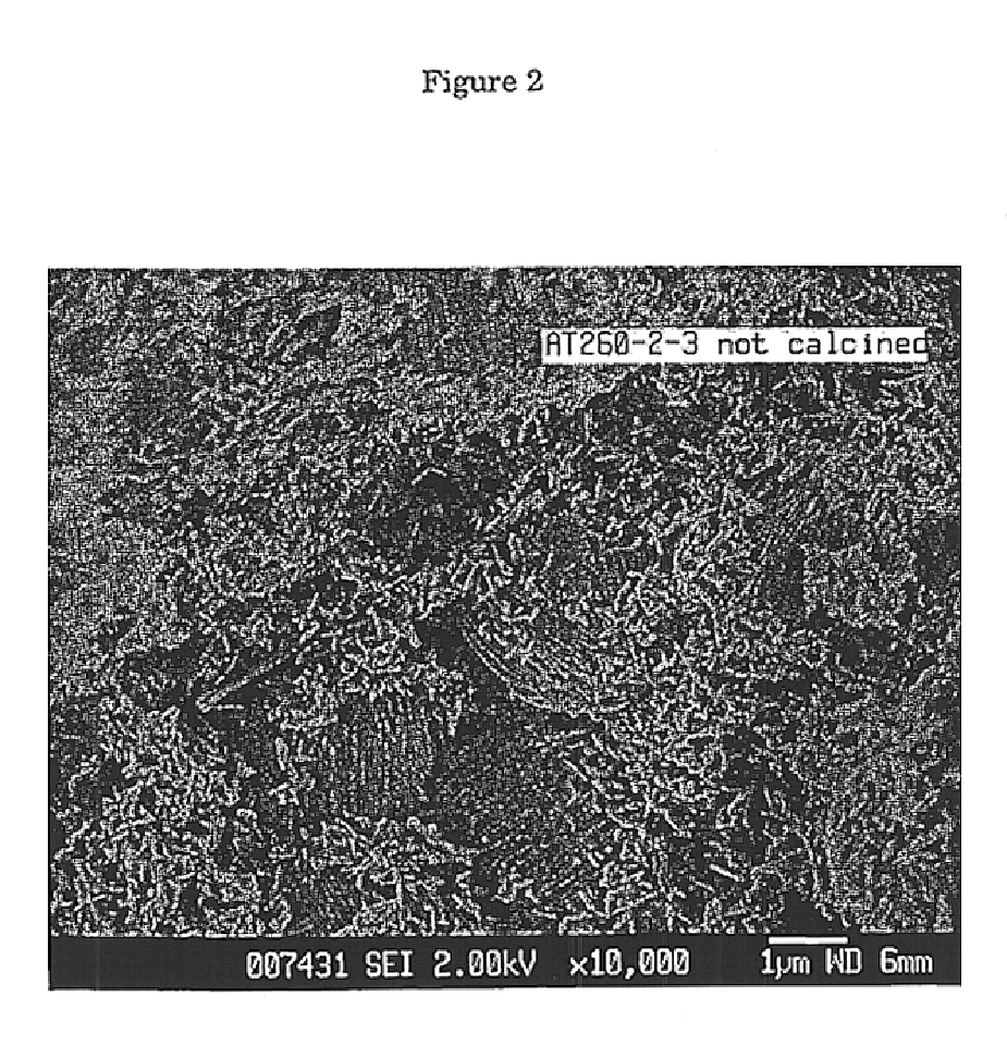
The product extrudates we...
example 3
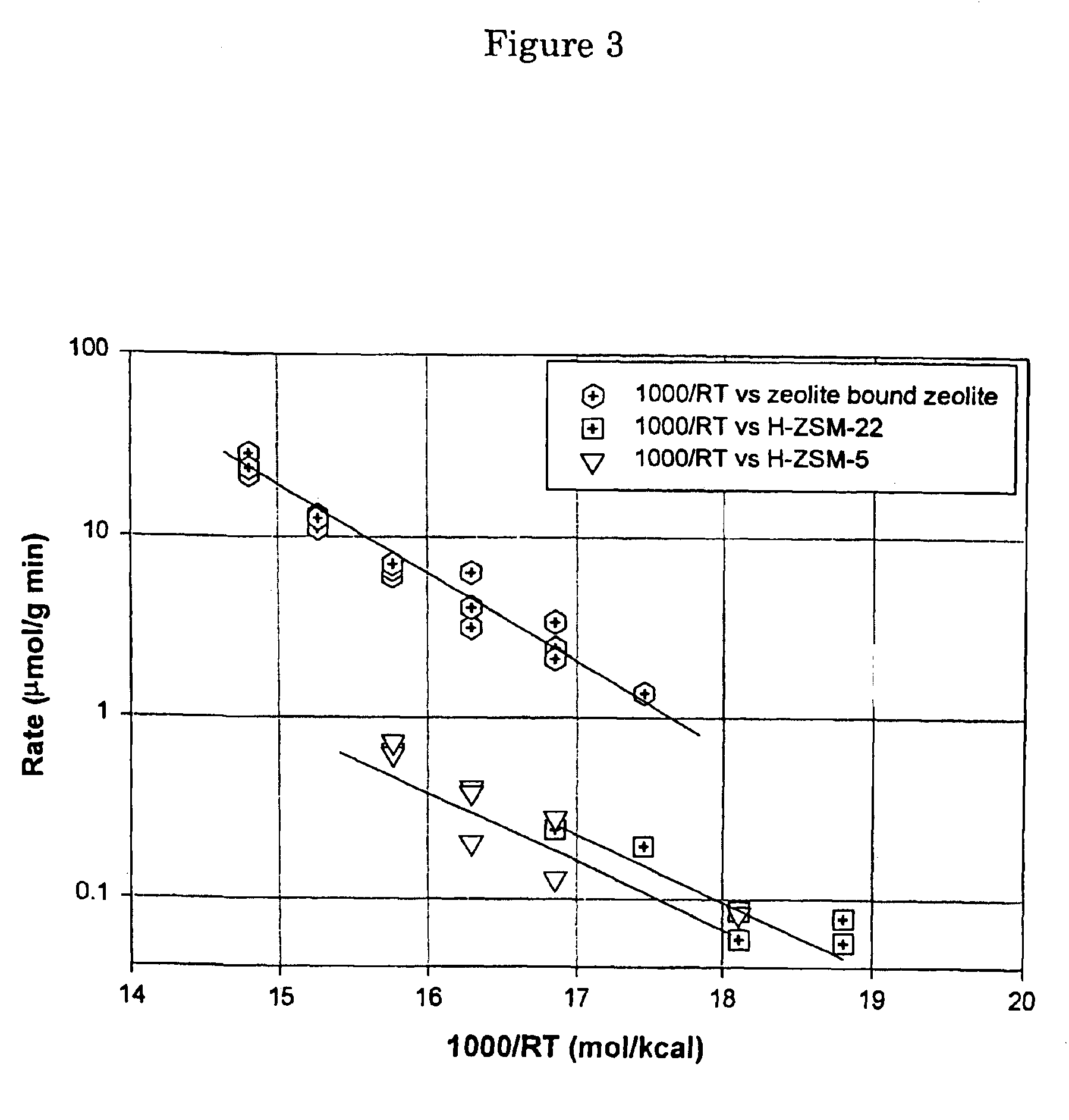
The zeolite bound zeolite prepared according to Example 1 was used for the disproportionation of toluene.
Before packing into a stainless steel reactor, one gram of the zeolite bound zeolite was mixed with 1 gram of 80-100 ultra-pure quartz sand. The catalyst was pretreated at 500 degrees C. with H2 for two hours followed by co-feed of toluene and hydrogen. The total pressure of the reaction was controlled at 45 psig. The partial pressure of toluene feed was 5.4 psia and partial pressure of H2 feed was 54 psia. The toluene flow rate was 36.7 mmol / hr. The hydrogen stream was controlled by a Brooks mass flow controller and the toluene feed was pumped by a high pressure liquid pump. The experiment was preformed under differential regimes so that the reaction rate could be measured. All products were analyzed by an on-line HP 6890 GC equipped with Chirasil DEX CP and DB1 columns.
PUM
| Property | Measurement | Unit |
|---|---|---|
| Temperature | aaaaa | aaaaa |
| Temperature | aaaaa | aaaaa |
| Temperature | aaaaa | aaaaa |
Abstract
Description
Claims
Application Information