
Mixer circuit and differential amplifier circuit

a technology of mixer circuit and amplifier circuit, which is applied in the field of differential amplifier circuit and mixer circuit, can solve the problems of reducing the performance of communication equipment with the structure of the conventional rf mixer circuit, requiring multi-stage amplifiers, and amplification of extremely weak signals using transmitted/received rf frequencies in equipment such as terminal devices or wireless base stations used for information communication, so as to reduce power consumption and distortion in outputs.

Inactive Publication Date: 2005-02-22
PANASONIC CORP
View PDF5 Cites 18 Cited by
  • Summary
  • Abstract
  • Description
  • Claims
  • Application Information

AI Technical Summary

Benefits of technology

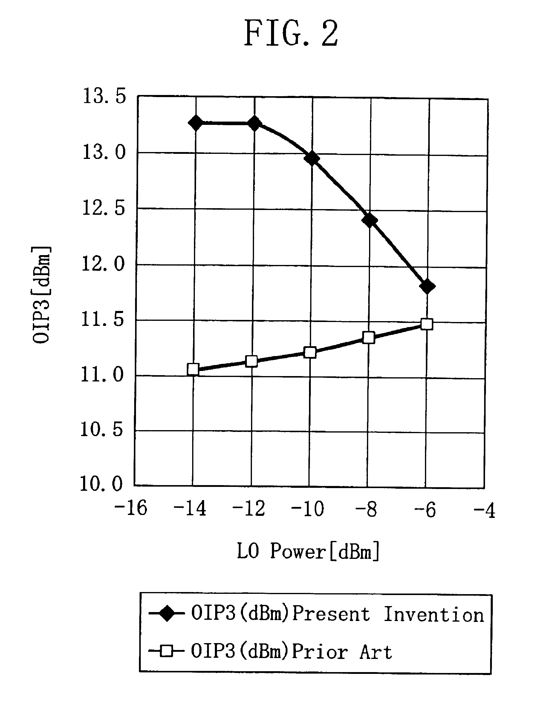
It is therefore an object of the present invention to provide an RF mixer circuit that has been reduced in power consumption and in distortion in the outputs resulting from a harmonic signal and a differential amplifier circuit usable in the RF mixer circuit.
The differential amplifier circuit has: a first current source connected to the first transistor; a second current source connected to the second transistor; a second inductor connected between the first transistor and the first current source; and a third inductor connected between the second transistor and the second current source. The arrangement reduces noise contained in the amplified RF signal and reduces the non-linearity of the output. Since the power consumption of an inductor is lower than that of a resistor, power consumption can also be reduced compared with that of the conventional differential amplifier circuit.

Problems solved by technology

The amplification of extremely weak signals with transmitted / received RF frequencies in equipment such as a terminal device or a wireless base station used for such information communication is not only costly but also requires multi-stage amplifiers.
On the other hand, odd-order harmonics such as the third and fifth harmonics are not cancelled by the conventional RF mixer circuit and appear in outputs so that it has been impossible to suppress distortion in the outputs caused by the odd-order harmonics.
In terms of transistor characteristics, distortion is more likely to occur with higher frequencies so that trouble caused by harmonics are particularly conspicuous with RF frequencies.
Thus, it has been difficult to implement smaller-size and higher-performance communication equipment with the structure of the conventional RF mixer circuit.
However, power is consumed in the resistors 202 and 203 so that the effect of reducing signal distortion is limited in design aiming at lower power consumption.
Therefore, it has been difficult to simultaneously achieve lower distortion and lower power consumption in the conventional RF mixer circuit.
Since odd-order distortion leads to troubles in equipment when the differential amplifier circuit is used alone, it has been requested to reduce harmonics without increasing power consumption.

Method used


Image

  • Mixer circuit and differential amplifier circuit
  • Mixer circuit and differential amplifier circuit
  • Mixer circuit and differential amplifier circuit

Examples


embodiment 1

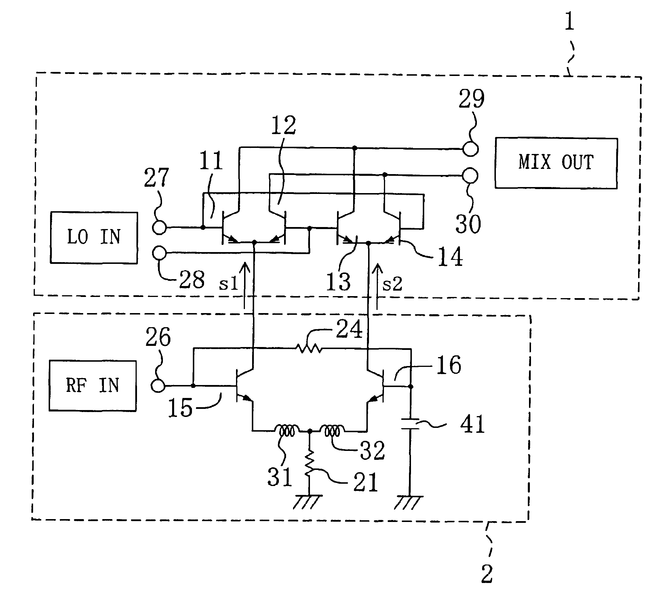
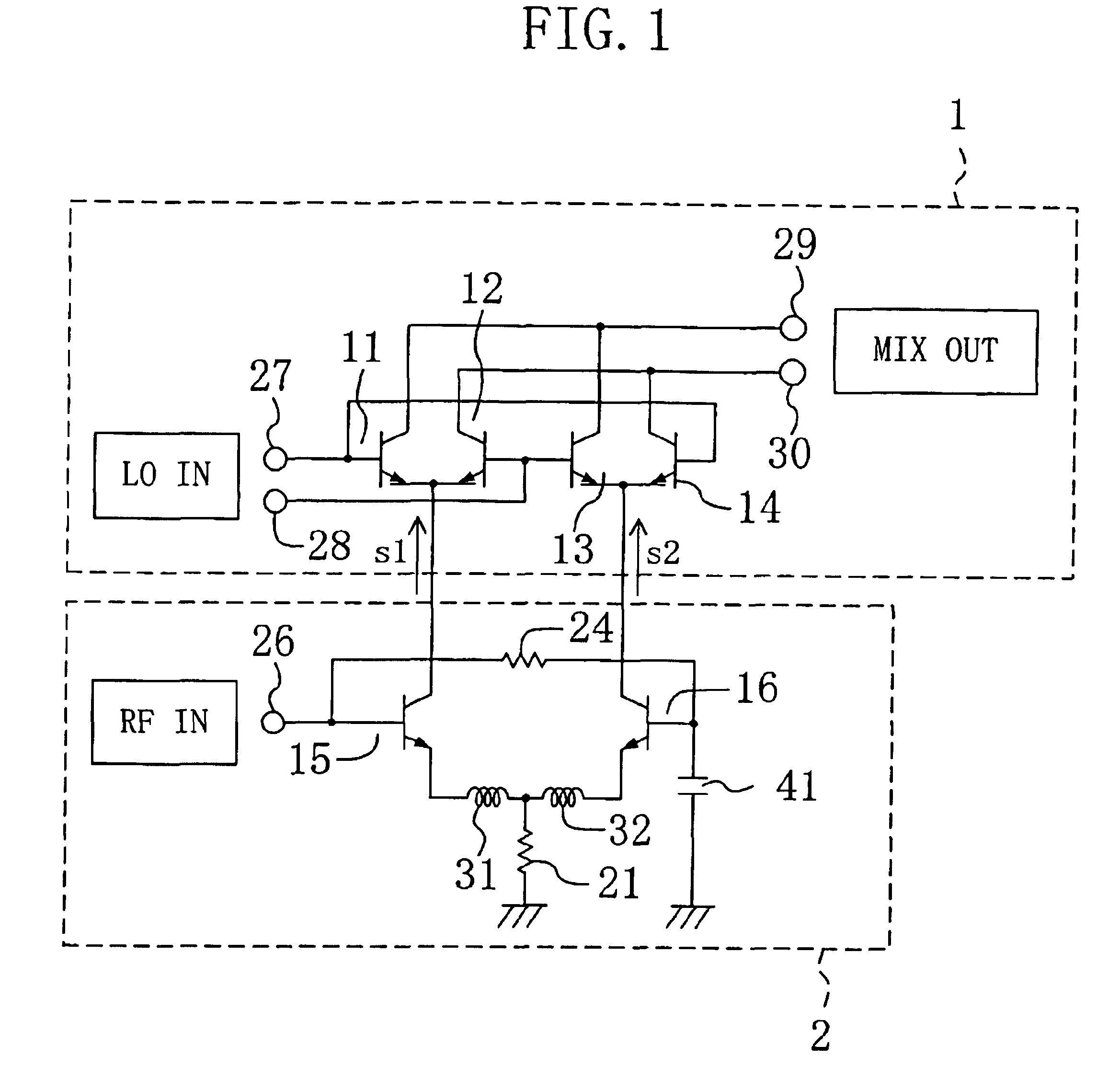
FIG. 1 is a circuit diagram showing a structure of an RF mixer circuit according to a first embodiment of the present invention.

As shown in the drawing, the RF mixer circuit according to the present embodiment is composed of a differential amplifier circuit 2 and a double-balanced mixer circuit (DBM circuit) 1 connected to the differential amplifier circuit 2.

When an RF signal is inputted to the differential amplifier circuit 2 and an LO signal and an inverted LO signal opposite in phase to the LO signal are inputted to the DBM circuit 1 in the RF mixer circuit according to the present embodiment, these signals are mixed with each other in the DBM circuit 1 so that an IF signal as a mixed signal of the RF signal and the LO signals is outputted in the same manner as in the conventional RF mixer circuit.

In the RF mixer circuit according to the present embodiment, harmonic components contained in the outputs of the differential amplifier circuit 2 have been reduced compared with those ...

embodiment 2

FIG. 4 is a circuit diagram showing a structure of an RF mixer circuit according to a second embodiment of the present embodiment.

As shown in the drawing, the RF mixer circuit according to the present embodiment is different from the RF mixer circuit according to the first embodiment in that a third inductor 25 is provided in place of the first resistor 24 (see FIG. 1). As for the other circuit components, they are the same as those used in the first embodiment.

Briefly, the RF mixer circuit according to the present embodiment is composed of a DBM circuit 1 having the same structure as that of each of the conventional and first embodiments and of a differential amplifier circuit 2.

The differential amplifier circuit 2 has: first and second bipolar transistors 15 and 16 having respective bases to which RF signals having a 180° phase shift therebetween are inputted; first and second inductors 31 and 32 connected to the respective emitters of the first and second bipolar transistors 15 a...

embodiment 3

As a third embodiment of the present invention, a differential amplifier circuit which outputs an amplified signal in response to an inverted input signal opposite in phase to an input signal will be described.

FIG. 5 is a circuit diagram showing a structure of the differential amplifier circuit according to the present embodiment. As shown in the drawing, the differential amplifier circuit according to the present embodiment is identical to the differential amplifier circuit 2 (see FIG. 1) in the RF mixer circuit according to the first embodiment. The RF signal input port 26 according to the first embodiment is replaced with an input port 53 in the present embodiment. In addition, output ports 50 and 51 for outputting signals are provided.

The differential amplifier circuit according to the present embodiment has: first and second bipolar transistors 15 and 16 having respective bases connected to each other; and the input port 53 connected to each of the respective bases of the first...


PUM


Abstract

A mixer circuit is composed of a differential amplifier circuit and a DBM circuit. The differential amplifier circuit has a first bipolar transistor, a second bipolar transistor, a first resistor provided between the respective bases of the first and second bipolar transistors, and a capacitor provided between the base of the second bipolar transistor and the ground. Since the first resistor and the capacitor are provided such that the circuit undergoes RC oscillation in response to the third harmonic of an input signal, the third and higher-order harmonics can be reduced.

Description

BACKGROUND OF THE INVENTIONThe present invention relates to a differential amplifier circuit and a mixer circuit using the same and capable of integration and, more particularly, to a differential amplifier circuit and a mixer circuit which can be used in equipment for mobile communication.In the field of information communication, the development of technologies using higher RF frequencies including wideband CDMA using RF frequencies in the 2 GHz range, Bluetooth using RF frequencies in the 2.4 GHz range, and a wireless LAN using further higher RF frequencies has advanced recently.The amplification of extremely weak signals with transmitted / received RF frequencies in equipment such as a terminal device or a wireless base station used for such information communication is not only costly but also requires multi-stage amplifiers. It is therefore normal practice to convert RF frequencies received from, e.g., an antenna to signals at lower frequencies. In such a case, an RF mixer circu...

Claims


Application Information

Patent Timeline
Patent Type & Authority Patents(United States)
IPC IPC(8): G06F7/556G06G7/16G06F7/48G06G7/00H03F3/45H03D7/14H03F3/21
CPCH03D7/1433H03F3/211H03F3/4508H03D7/1441H03D7/1491H03F2200/294H03D2200/0023H03F2203/45464H03F2203/45316
Inventor WATANABE, DAISUKEITOH, JUNJIIMANISHI, IKUO
Owner PANASONIC CORP
Learn More