Purified water supply system for high demand devices and applications

a technology of high-demand devices and water supply systems, applied in the field of water supply systems, can solve the problems of alarm state and possible automatic shut-down, significant negative impact of a centralized water supply system, and danger to the dialysis patient(s), and achieve the effect of increasing operational effectiveness and/or efficiency and constant movemen

Inactive Publication Date: 2005-03-01
GAMBRO RENAL PROD
View PDF8 Cites 57 Cited by
  • Summary
  • Abstract
  • Description
  • Claims
  • Application Information

AI Technical Summary

Benefits of technology

Other industrial water usage machines and water supply circuits may also suffer similar drawbacks. Such systems may include pharmaceutical preparation processes and / or electronic device (e.g., microchip) manufacturing processes. Thus, any system that may include the use of both low and high water demand devices on a water supply line may take advantage of the present invention.
Hence, a need exists for providing for a safe, non-overburdensome connection of high water demand devices, like dialyzer re-use machines, to a water supply line so that other lower demand machines, such as dialysis machines, may be provided with a sufficient, uninterrupted supply of water volume, pressure and / or flow rates to maintain normal operations. It is toward this and related aims that the present invention is directed.
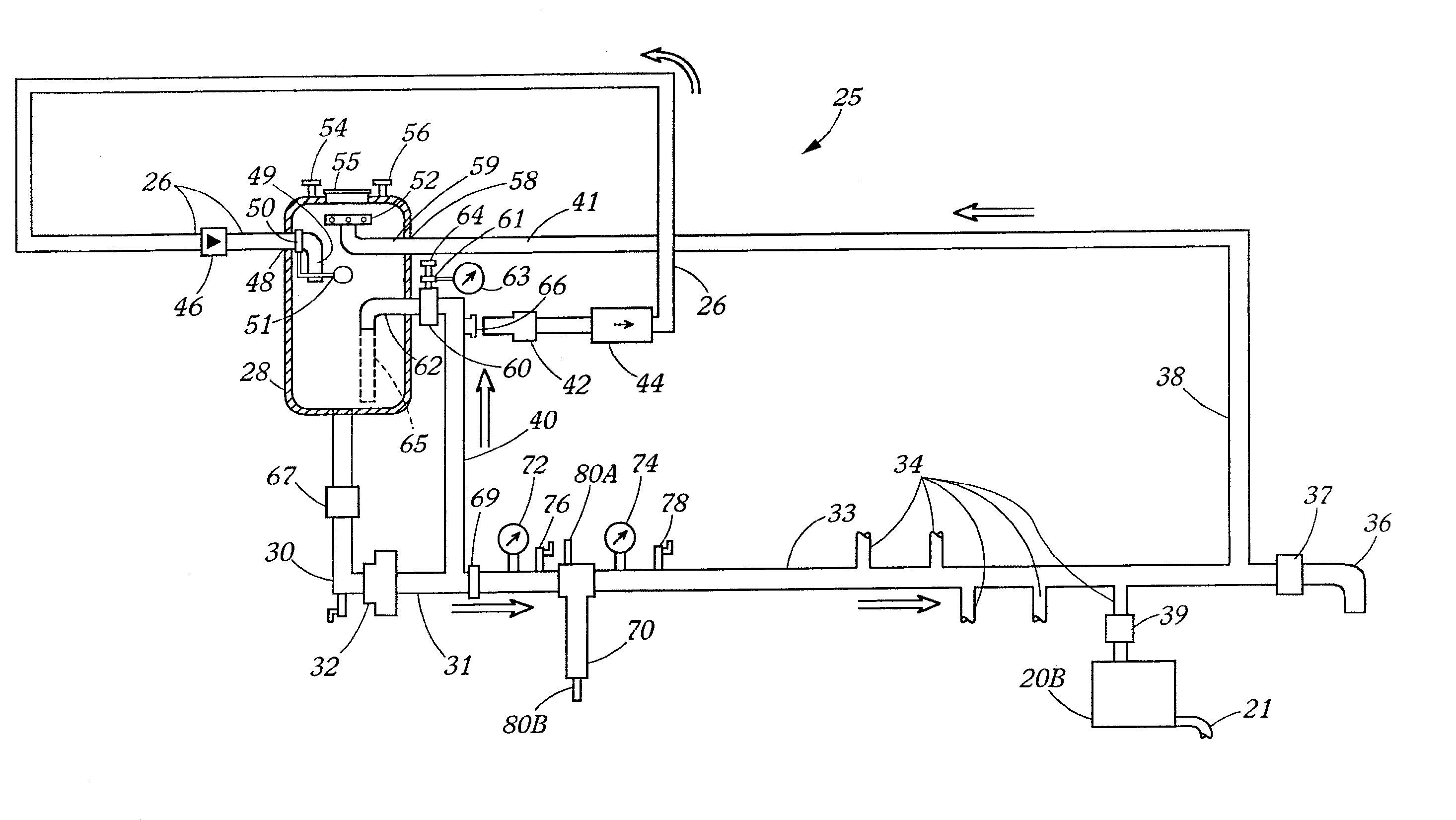
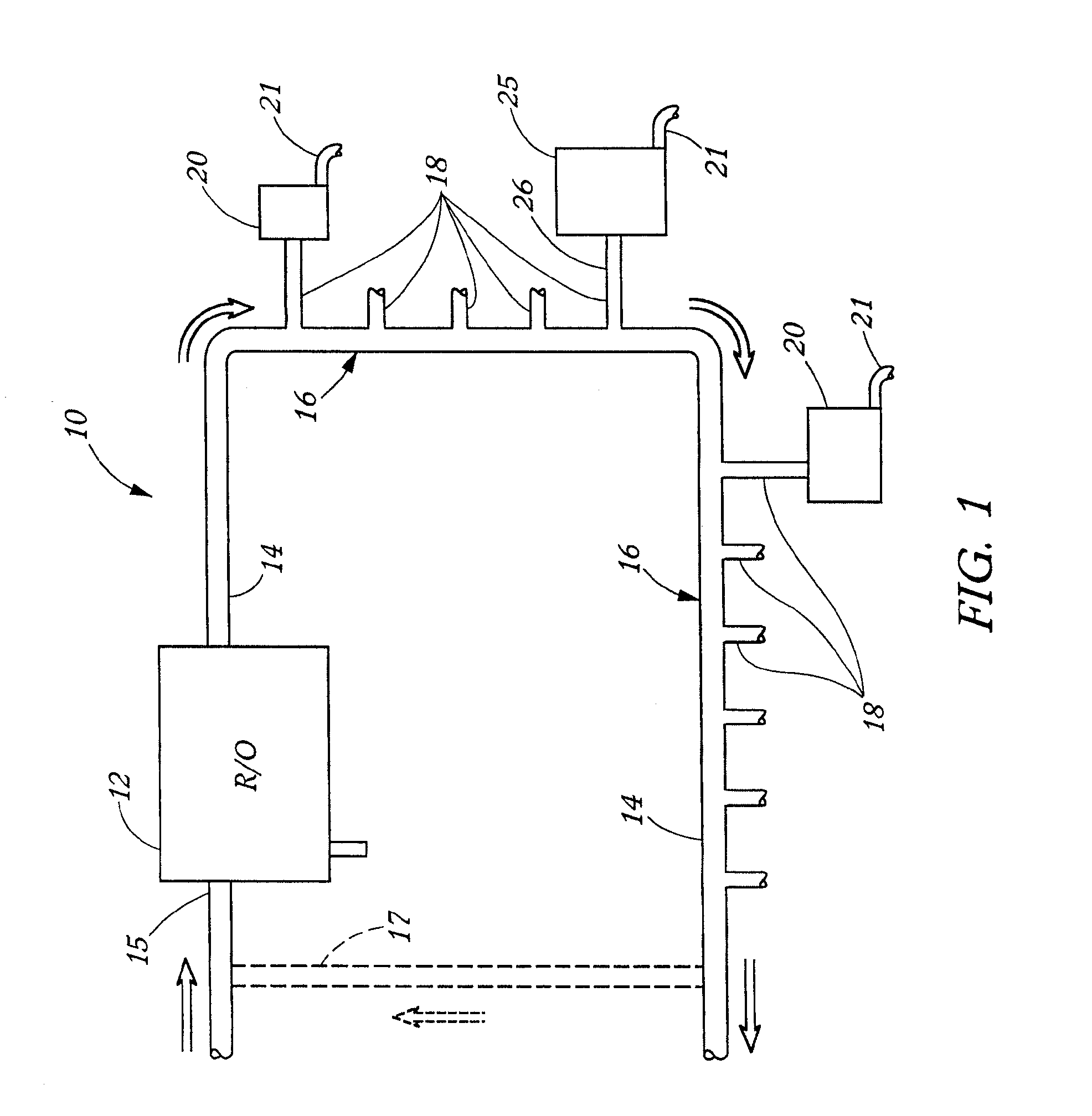
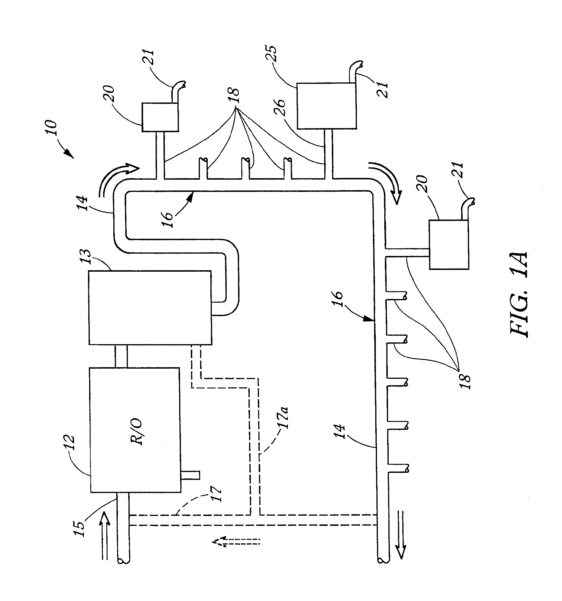
The present invention is directed to the provision of a water supply sub-system, which is connectable to a centralized or main water supply system. The sub-system provides for the connection of one or more relatively high demand water using devices in a substantially isolated or lower demand disposition relative to the main water circuit. Generally, the present sub-system includes a sub-system storage tank, which is connectable to the main water supply system, and a sub-system water line to which the high demand device or devices may be attached. This sub-system water line (also referred to in some recirculatable embodiments as a loop, see below) is connected to and leads from the sub-system storage tank, through a pump to one or more outlet connections for a potential variety of generally high volume flow rate demand, short duration water use devices such as dialyzer re-use machines. This further sub-system water line may be dead ended (thus, no loop), or run to a drain or drain connection, or more preferably, it may feed back to the sub-system storage tank for recirculation therethrough (and, thus form a loop). A shunt line may additionally or alternatively be connected to the sub-system water line to provide pressure control for the output from the pump, and / or for more directly feeding from the pump back to the storage tank for the same or perhaps a similar general recirculation purpose. At least one of these recirculation lines preferably feeds into or near the top of the storage tank and feeds through a spray head arrangement therein (thus completing the loop) which disperses the incoming water in a substantially continual spray configuration to maintain a substantially constant movement, non-stagnating air to water interface within the tank. This assists in maintaining a preferably more sterile environment within the storage tank. The other feedback line may preferably feed into a lower part of the storage tank to counteract vortex action at the tank outlet. A microbiological filter and / or various other components may also be included in or along the sub-system water line to ensure and / or increase operational effectiveness and / or efficiency.
In use, purified water may be taken into the sub-system storage tank from the centralized supply system at a substantially controlled, relatively constant low rate so that a substantially no or low fluctuation demand is presented by the sub-system to the central or main supply system. The tank can then feed a short duration, higher volume flow rate to the rest of the sub-system, which, including one or more high water demand devices, can then draw the respective higher flow, higher volume demands from the outflow of the sub-system storage tank while the storage tank continues to draw the preferably constant, substantially lower maximum volume flow rate from the main supply system. This high demand draw may have the effect of drawing down the total volume contained within the sub-system storage tank, but does so generally for only a comparatively short duration and preferably not to an empty state. The maximum intermittent high demands of the high demand devices may thus be accounted for within the total operating storage tank volume. The high demand devices may then be operated at any time during which the storage tank contains a sufficient residual water volume without then impacting on or interrupting the main supply of water to the lower demand, longer duration dialysis or like machines connected directly to the main line.
As noted, systems of the present invention may be highly beneficial in purified water supply systems such as in medical applications like dialysis, or may also be useful in pharmaceutical preparation or electronics manufacturing or other water supply processes.

Problems solved by technology

The high demands of one or more re-use machines connected to a main supply line can then significantly negatively impact a centralized water supply system having an R / O unit which directly feeds water at a constant maximum output.
The negative impact of the high demand is such that it may overburden the main water supply system by drawing too much water flow from the main supply line to the point that the flow of purified water provided simultaneously to any other water using machines such as one or more dialysis machines may be reduced, interrupted or the central line pressure may be decreased sufficiently so that one or more of the dialysis machines do not have sufficient water volume or pressure to continue producing dialysate and / or replacement fluid, as needed for the dialysis procedure, and may thus be forced into an alarm state and possible automatic shut-down.
Such alarms and possible shut downs may then provide a danger to the dialysis patient(s).
However, such tanks have been disposed in the primary water circuit, and as such are often necessarily unacceptably too large (approximately 250 gallons) for many medical / dialysis settings and / or have too many stagnation areas (as in bladder surge tanks) thus providing unacceptable opportunities for undesirable biological and / or microbiological growth.
There are usually large pressure drops through such piping systems due to the high flow rates and long lengths of the piping system as well as due to the number of taps for each water using unit to be attached to the piping system.
Intermittent high demand devices such as dialyzer re-use equipment draw large amounts of water out of the piping system in a short period of time.
This may cause the pressure levels to drop sharply throughout the piping system, thereby likely causing both the re-use equipment and any other attached water-using equipment, such as dialysis machines, to not have sufficient water volume and / or pressure to operate properly.
Other industrial water usage machines and water supply circuits may also suffer similar drawbacks.

Method used


Image

  • Purified water supply system for high demand devices and applications
  • Purified water supply system for high demand devices and applications
  • Purified water supply system for high demand devices and applications

Examples


Embodiment Construction

A centralized or main water supply system 10 is shown in FIGS. 1 and 1A including a water treatment or purifying unit 12 which feeds purified water either directly into an outlet purified water supply line 14 (FIG. 1) or indirectly to line 14 via an intervening storage tank 13 (FIG. 1A). Unit 12 is preferably here a reverse osmosis (R / O) or de-ionization (DI) unit 12, and either of these or other types of treatment units may be considered here even if R / O is used in the description here. Water line 14 is the distribution line, which may also be referred to as the main line 14 herein to distinguish it from various other water lines to be described throughout this specification. An inlet feed line 15 which feeds into treatment unit 12 will be understood as feeding water from any of various sources or combinations of sources (none shown) such as from a tap and / or from one or more pre-treatment or filtration devices (carbon and / or mechanical filter(s) and / or chemical or water softening ...


PUM

PropertyMeasurementUnit
pressureaaaaaaaaaa
pressureaaaaaaaaaa
dwell timeaaaaaaaaaa

Abstract

A water supply sub-system for connection to a main water supply system includes a storage tank having an inlet with a flow control valve for connection to the main water supply system. The sub-system may be disconnected from the main system and configured as a closed system for disinfecting the sub-system. An outlet line connects the storage tank to a pump that pumps water from the tank to a sub-system supply line. One or more branch connections may connect the sub-system supply line to high-demand water using devices, such as dialysis machines. The supply line may be a feedback loop. A shunt feedback loop parallel to the feedback loop of the supply line has a pressure control valve that regulates pressure in the supply line feedback loop. A filtration device may also be included to ensure the purity of the water circulating through the sub-system.

Description

BACKGROUND OF INVENTIONThe present invention relates generally to water supply systems, and more particularly to a system adapted for supplying purified water to one or more water using devices, some of which having distinctive water consumption demands, including devices having distinctively and usually intermittently high demands versus devices having low demands for flow rates and / or volumes of purified water. This invention further presents particular advantages in medical and like high quality purified water supply systems such as in allowing for the supply of water to both high demand dialyzer reprocessing machines and lower demand dialysis machines without substantially increasing the total operational volume or flow rate of purified water flowing through the entire water supply system.There are presently a variety of industrial and medical devices and associated procedures that require the use of purified water. A prominent example is found in medical dialysis. In such dialy...

Claims


Application Information

Patent Timeline
Patent Type & Authority Patents(United States)
IPC IPC(8): B01D61/10B01D61/08B01D61/58B01D61/02B01D61/14C02F1/44A61M1/16
CPCB01D61/02B01D61/08B01D61/145B01D61/58C02F1/44B01D61/10A61M1/1656A61M2205/84B01D61/025C02F1/444C02F1/441A61M1/1668Y10T137/86035Y10T137/85954Y10T137/0402Y10T137/0318Y10T137/0396
Inventor MULLINS, STEPHEN M.LUEHMANN, DOUGLAS A.BIELEFELD, JOHN D.
Owner GAMBRO RENAL PROD
Why Eureka
Try Eureka