Dew point humidifier (DPH) and related gas temperature control

a humidifier and dew point technology, applied in flow mixers, combustion air/fuel air treatment, secondary air addition to fuel, etc., can solve the problems of difficult humidity control, uncertainty as to just how much humidity has been imparted, and typical bubbling-type humidifiers cannot deliver 100% relative humidity, etc., to achieve simple and easy control, simple, economic and effective

Inactive Publication Date: 2005-03-08
ZHANG CHAOJIONG
View PDF19 Cites 29 Cited by
  • Summary
  • Abstract
  • Description
  • Claims
  • Application Information

AI Technical Summary

Benefits of technology

It is therefore an object of the invention to provide a gas humidifier that is simple and easy to control to precisely produce saturated gas at the dew point. It is a further object of the invention to provide a method of humidifying gas with such a humidifier. It is yet another object of the invention to provide a gas humidifier that produces saturated gas at the dew point over a wide range of temperatures using a single measured parameter (temperature) within the enclosure without dew point “calibration”. It is another object of the invention to provide simple, economic, and effective means to further heat and trace the gas temperature after humidification.
In order to realize these and other features and advantages of the invention, enhanced thermal insulation is provided between the steam generating boiler and bulk water within the vessel and/or the pre-humidifier. The thermal insulation prevents direct heating of bulk water or pre-humidified gas by heat from the boiler. Thus, thermal energy from a heating element with the steam generating boiler is contained with the boiler to only generate vapor. Heat is therefore passed to the gases only through gas-vapor mixing and/or vapor condensing.
Although the boiler is thermally isolated from other functions of the gas humidifier, openings at the bottom of the boiler are provided so that bulk water from the vessel flows back into boiler. This arrangement eliminates the necessity of a separate water supply and recycling system and further provides water leveling for the pre-humidifier, the condenser/water separator

Problems solved by technology

However, typical bubbling-type humidifiers cannot deliver 100% relative humidity to gases and only allow relatively low gas flow rate for a certain cross area of humidifier.
Another disadvantage of this method is its uncertainty as to just how much humidity has been imparted to gases as the gases leave the outlet of the humidifier.
In bubbling-type humidifiers, it is difficult to control humidity unless using a feedback signal developed from the measurement of actual humidity value at the humidifier outlet.
Even with such controls, the bubbling-type humidifier requires a relatively large cross section area and water height to humidify the gas and the response time for change of humidity is very long.
In order to maintain good control of the dew point temperature, these types of humidifiers are usually bulky, complicated, and expensive with very low energy efficiency.
Because of this phenomenon, the temperature and humidity of the gas-vapor mixture is rather difficult to control.
Further, the difficulty of control increases as the rate of gas flow increases because the amount of heat absorbed from the water is relatively high.
Further, a specialized membrane is required, increasing the overall cost of such a system.
Again, there is no mechanism to guarantee precise humidity control without further condensation or employment of a humidity sensor.
However effective such self-humidification may be in a laboratory environment, it is difficult for commercial manuf

Method used


Image

  • Dew point humidifier (DPH) and related gas temperature control
  • Dew point humidifier (DPH) and related gas temperature control
  • Dew point humidifier (DPH) and related gas temperature control

Examples


Embodiment Construction

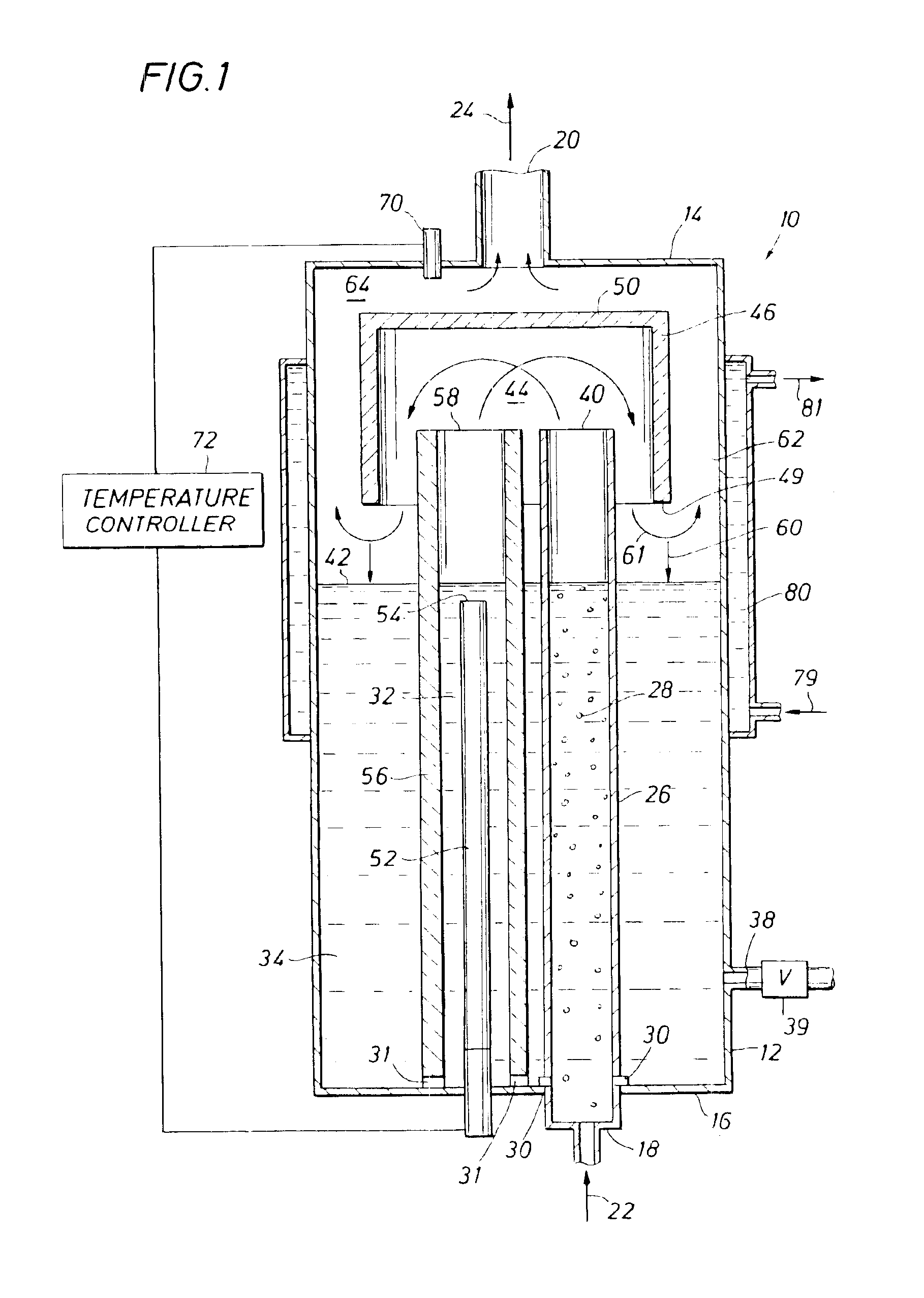
FIG. 1 show the core structure of a humidifier 10 and a method humidifying gas, in accordance with the present invention. The humidifier 10 principally comprises a vessel 12, preferably cylindrical in aspect, with a top 14 and a bottom 16. An inlet line 18 introduces dry gas into the vessel 12, and an outlet 20 directs humidified gas from the vessel. Dry gas is shown entering the vessel by an arrow 22 and humidified gas is shown exiting the vessel by an arrow 24.

The dry gas 22, which is at a lower temperature than set dew point temperature, is initially humidified by flowing through pre-humidifier 26. The dry gas 22 bubbles up through the pre-humidifier 26 forming bubbles 28, which rise up through the pre-humidifier, thereby picking up some moisture and being warmed to a higher temperature by the water in the pre-humidifier column. The pre-humidifier 26 defines an elongated container, such as a tube, with openings 30, preferably along the bottom of the tube inside the vessel. The op...


PUM

PropertyMeasurementUnit
Temperatureaaaaaaaaaa
Flow rateaaaaaaaaaa
Gravityaaaaaaaaaa

Abstract

A method of humidifying gases to 100% relative humidity and a humidifier to carry out such a method are provided to humidify gases for fuel cells and for other applications. The humidification of gases is thermally controlled and thermal energy is managed to provide an efficient system. A pre-humidifier accommodates a wide range of flow rates of dry gas to initially humidify and pre-heat the gas, and a boiler provides steam to mix with the effluent from the pre-humidifier to humidify the gas to saturation. A thermal insulator between the boiler and bulk water and/or pre-humidifier enhances the steam generation from the boiler and prevents direct heating of water or gases by heat from the boiler. Above the boiler, bulk water, and pre-humidifier, a mixing chamber further functions as a condenser and water separator. The mixing chamber provides a space for mixing gases and steam and separates saturated gases from condensed water. By vapor condensation during the mixing, the gas can be humidified completely to its dew point at given temperature and pressure conditions.

Description

FIELD OF INVENTIONThe present invention relates generally to the field of continuous flow gas humidification systems, and, more particularly, to a method and a system for humidifying gas reactants for fuel cells or other gases. It also relates to the field of temperature control and tracing of the humidified gas.BACKGROUND OF INVENTIONAs described in U.S. Pat. No. 6,338,472 to Shimazu et al., humidifiers, like those of the field of the present invention, are typically used to humidify process gases supplied to an anode or a cathode of a Solid Polymer Fuel Cell (SPFC). The process gases comprise a fuel gas provided to the anode and an oxidizing gas provided to the cathode. A solid polymer fuel cell generates electrical energy by electrochemical reactions in which protons generated from a fuel supplied to the anode transfer to the cathode through an electrolyte membrane and react with an oxidizing gas supplied to the cathode to produce water. The humidifier of the present invention, h...

Claims


Application Information

Patent Timeline
IPC IPC(8): B01D47/00B01F3/04B01D1/00B01D1/14B01D3/34B01F5/06F24F3/04F24F6/00G05D22/00G05D22/02H01M8/04H01M8/10
CPCB01F5/0603H01M8/04126H01M8/04164H01M8/04291Y02E60/50H01M2008/1095Y10S261/10B01F25/421
Inventor ZHANG, CHAOJIONG
Owner ZHANG CHAOJIONG
Why Eureka
Try Eureka