
Apparatus and method for integral bypass diode in solar cells

Inactive Publication Date: 2005-03-08
SOLAERO TECH CORP
View PDF16 Cites 57 Cited by
  • Summary
  • Abstract
  • Description
  • Claims
  • Application Information

AI Technical Summary

Benefits of technology

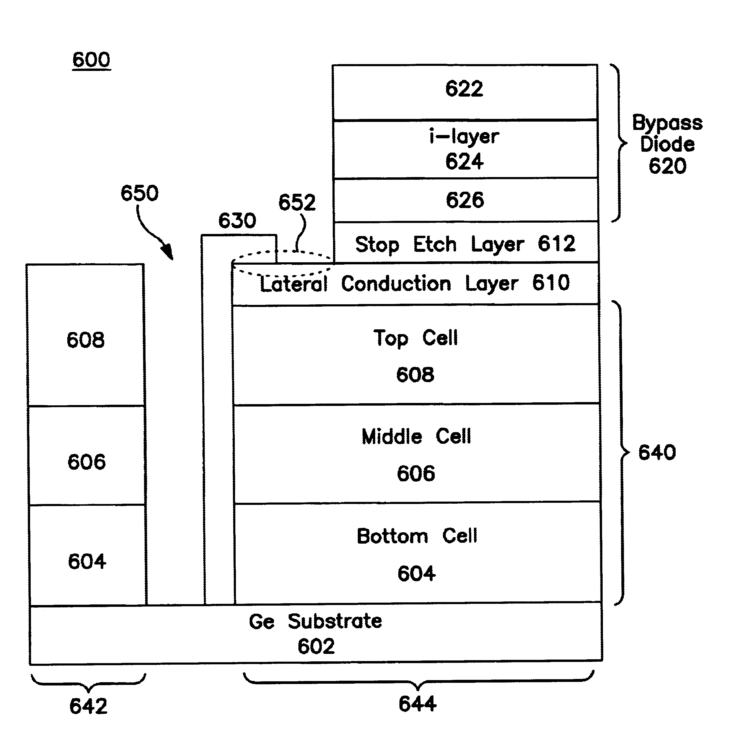
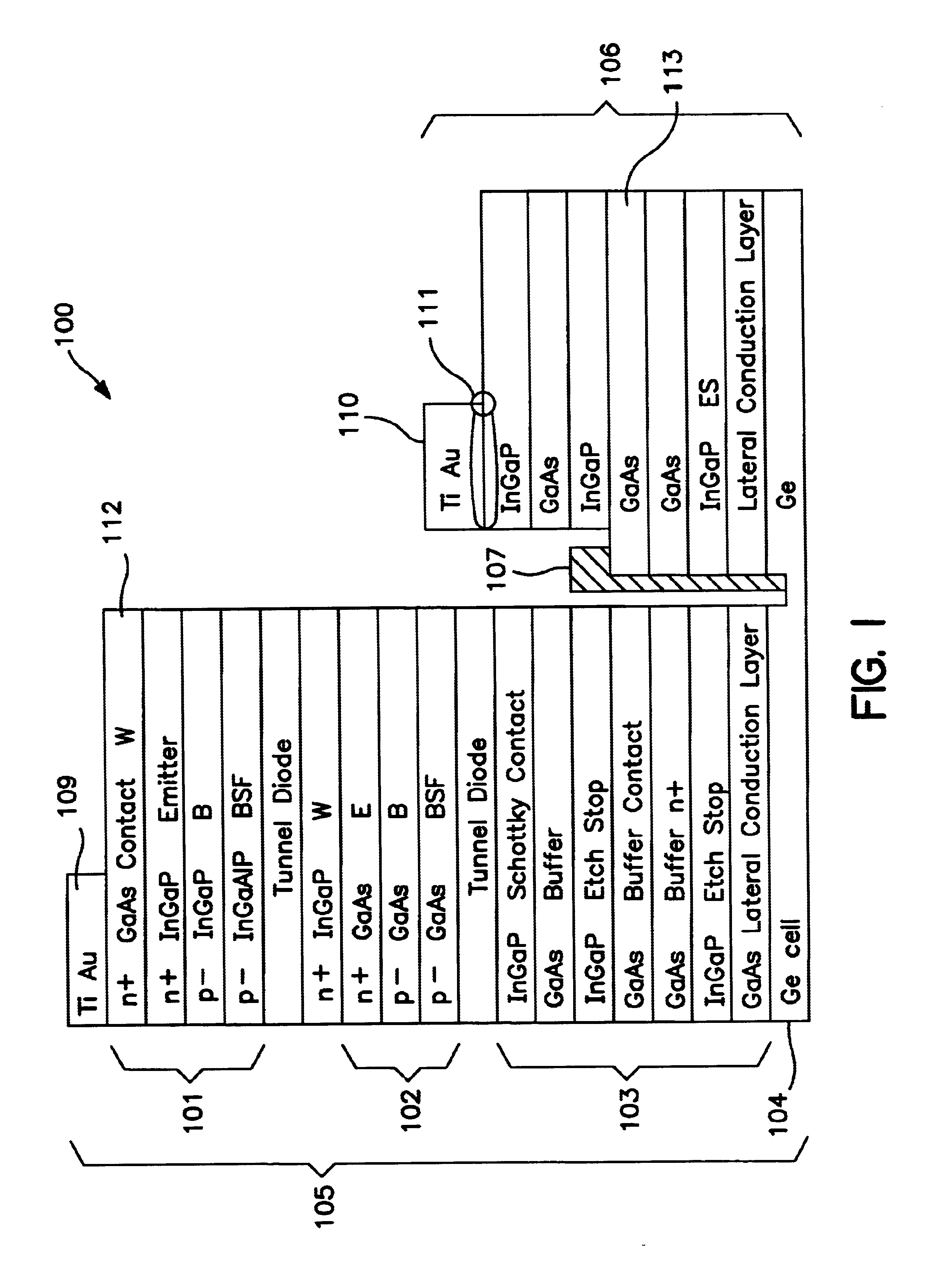
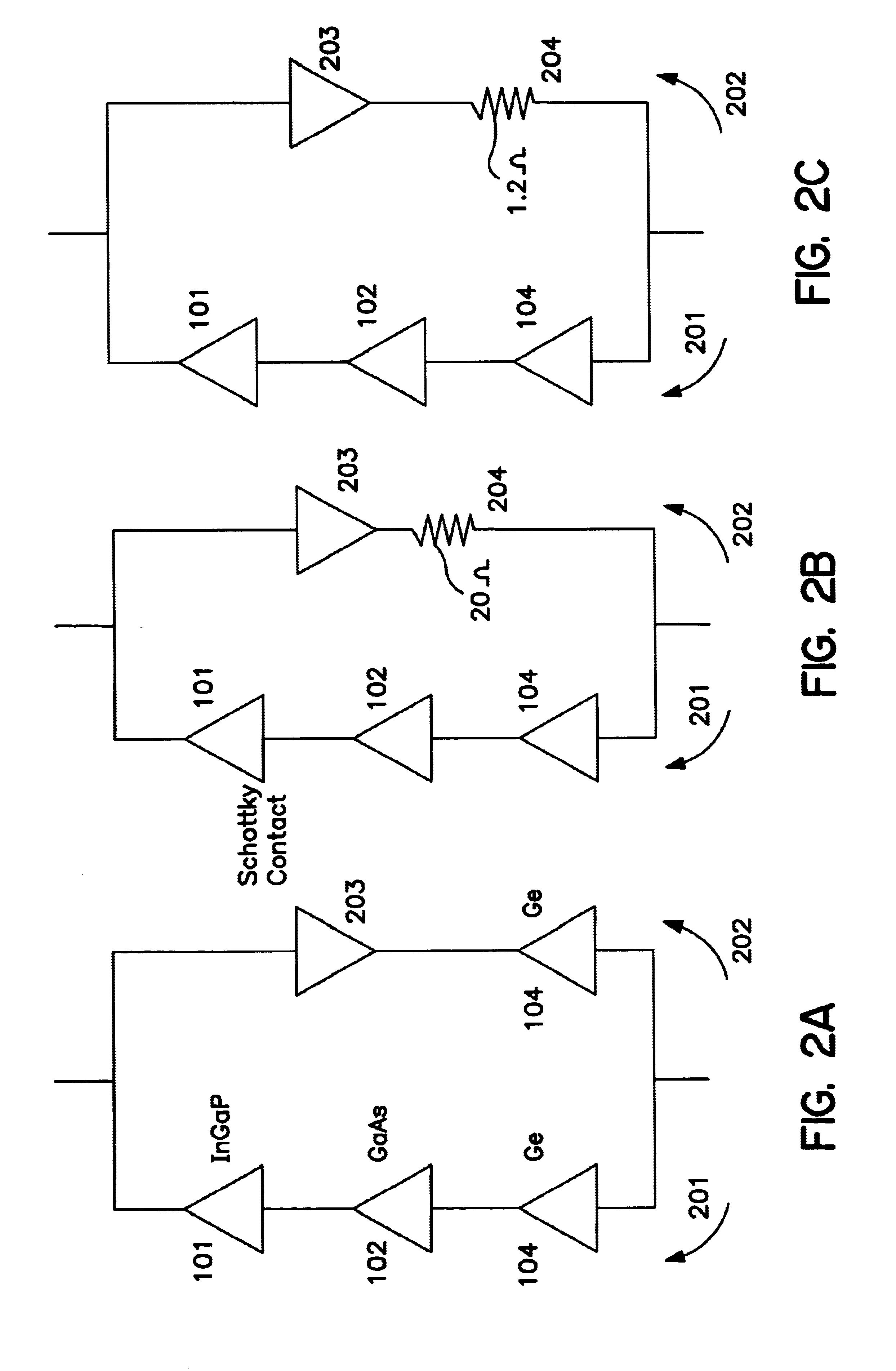
A solar device having a multifunction solar cell structure with a bypass diode is disclosed. The bypass diode provides a reverse bias protection for the multijunction solar cell structure. In one embodiment, the multifunction solar cell structure includes a substrate, a bottom cell, a middle cell, a top cell, a bypass diode, a lateral conduction layer, and a shunt. The lateral conduction layer is deposited over the top cell. The bypass diode is deposited over the lateral conduction layer. One side of the shunt is connected to the substrate and another side of the shunt is connected to the lateral conduction layer. In another embodiment, the bypass diode contains an i-layer to enhance the diode performance.

Problems solved by technology

While significant progress has been made in this area, the requirement for solar cells to meet the needs of more sophisticated applications has not kept pace with demand.
However, if any of the cells are not illuminated, because of shadowing or damage, those shadowed cells may be forced to become reversed biased in order to carry the current generated by the illuminated cells.
This reverse biasing can degrade the cells and can ultimately render the cells inoperable.
A problem associated with this type of bypass diode is that it is difficult to manufacture and also less reliable because the exterior assembly is performed by the array assemblers rather than the cell manufacturer.
However, a problem associated with this technique is that it complicates the manufacturing process and is more difficult to assemble the solar cell array.
Because of the fragility of the cells this technique is difficult to implement in a manufacturing line.

Method used


Image

  • Apparatus and method for integral bypass diode in solar cells
  • Apparatus and method for integral bypass diode in solar cells
  • Apparatus and method for integral bypass diode in solar cells

Examples


Embodiment Construction

A method and an apparatus of solar cell with multijunction solar cell structure having a bypass diode with an i-layer are described.

In the following description, for purposes of explanation, numerous specific details are set forth to provide a thorough understanding of the present invention. It will be apparent, however, to one skilled in the art that these specific details may not be required to practice the present invention. In other instances, well-known circuits and devices are shown in block diagram form to avoid obscuring the present invention.

It is understood that the present invention may contain transistor circuits that are readily manufacturable using well-known CMOS (“complementary metal-oxide semiconductor) technology, or other semiconductor manufacturing processes. In addition, the present invention may be implemented with other manufacturing processes for making digital devices.

The present invention relates to a multijunction solar cell with at least one integral mono...


PUM


Abstract

A solar cell having a multijunction solar cell structure with a bypass diode is disclosed. The bypass diode provides a reverse bias protection for the multijunction solar cell structure. In one embodiment, the multifunction solar cell structure includes a substrate, a bottom cell, a middle cell, a top cell, a bypass diode, a lateral conduction layer, and a shunt. The lateral conduction layer is deposited over the top cell. The bypass diode is deposited over the lateral conduction layer. One side of the shunt is connected to the substrate and another side of the shunt is connected to the lateral conduction layer. In another embodiment, the bypass diode contains an i-layer to enhance the diode performance.

Description

FIELD OF THE INVENTIONThe present invention relates to the field of semiconductor devices. More specifically, the present invention relates to the photovoltaic solar cells.DESCRIPTION OF THE RELATED ARTPhotovoltaic cells, also called solar cells, are one of the most important new energy sources that have become available in the past several years. Considerable effort has gone into solar cell development. As a result, solar cells are currently being used in a number of commercial and consumer-oriented applications. While significant progress has been made in this area, the requirement for solar cells to meet the needs of more sophisticated applications has not kept pace with demand. Applications such as satellites used in mobile and telephone communications have dramatically increased the demand for solar cells with improved power and energy conversion characteristics.In satellite and other space related applications, the size, mass, and cost of a satellite power system are dependent...

Claims


Application Information

Patent Timeline
IPC IPC(8): H01L27/142H01L31/072H01L31/06H01L31/00H01L31/04H01L31/0687H01L31/0725H01L31/0735
CPCH01L27/142H01L31/03046H01L31/0687H01L31/0725H01L31/184H01L31/1852H01L31/0735Y10S136/293Y02E10/544H01L27/1421H01L31/00Y02E10/548Y02P70/50
Inventor SHARPS, PAUL R.AIKEN, DANIEL J.COLLINS, DOUGSTAN, MARK A.
Owner SOLAERO TECH CORP
Learn More