Circumferential strain attenuator

a technology of attenuator and circumferential strain, which is applied in the direction of seismology for waterlogging, force measurement by measuring optical property variation, instruments, etc., can solve the problem of dampening of signal processing, and achieve the effect of high-sensitivity fiber optic sensors and high natural frequency of devices

Inactive Publication Date: 2005-03-22
WEATHERFORD TECH HLDG LLC
View PDF33 Cites 65 Cited by
  • Summary
  • Abstract
  • Description
  • Claims
  • Application Information

AI Technical Summary

Benefits of technology

e of the fluid within the pipe. An advantage of the present invention is that it provides the ability to selectively modify, or otherwise attenuate, the gain of a flowmeter while keeping other constraints constant. The present invention results in a flowmeter having a fixed fiber length with the capability to measure a wide range of pressure levels in various acoustic environments. It will be appreciated by those skilled in the art that the environment surrounding a flowmeter may produce too much acoustic energy and thereby overtax the highly sensitive fiber optic sensors. Such environments are those that include pumps, venturis, choke valves, or any other sources that causes noise orders of magnitude above that of normal pipe flow.
The present invention also includes a compliant material positioned between the circumferential strain attenuator and the pipe. As a result the relatively high natural frequencies of the device that might otherwise cause a signal-processing problem are dampened out.
The foregoing and other objects, features, and advantages of the present invention will become more apparent in light of the following detailed description of exemplary embodiments thereof.

Problems solved by technology

The design of fiber optic flowmeters are constrained by, among other things, the structural compliance of the pipe, optical timing issues for a given length of fiber, and slew rate limitations based on the rate of change of the length of the fiber sensors.
As a result the relatively high natural frequencies of the device that might otherwise cause a signal-processing problem are dampened out.

Method used


Image

  • Circumferential strain attenuator
  • Circumferential strain attenuator
  • Circumferential strain attenuator

Examples


Embodiment Construction

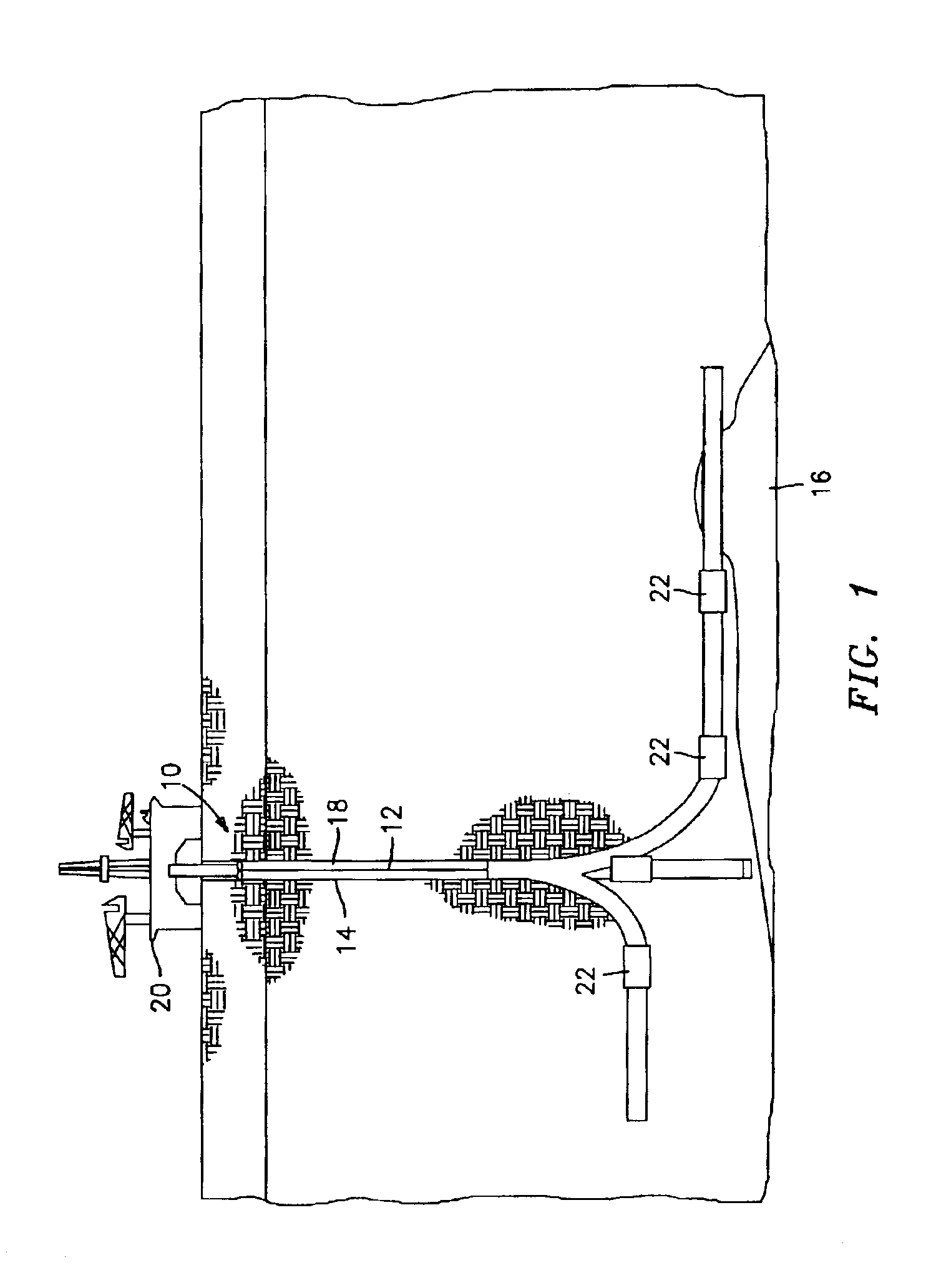
Referring to FIG. 1, there is shown an intelligent oil well system 10 containing one or more production pipes 12 that extend downward through a casing 14 to one or more petroleum sources 16. An annulus 18 is formed between the pipe 12 and the casing 14. Each production pipe 12 may include one or more lateral sections that branch off to access different petroleum sources 16 or different areas of the same petroleum source 16. Fluid mixtures, consisting mostly of petroleum products and water, flow from the sources 16 to the platform 20 through the production pipes 12. The production pipe 12 includes one or more the present invention apparatus 22 for non-intrusively sensing fluid flow within a pipe (also referred to hereinafter as a “flow meter”) to monitor various physical parameters of the fluid mixtures as they flow through the production pipes 12.

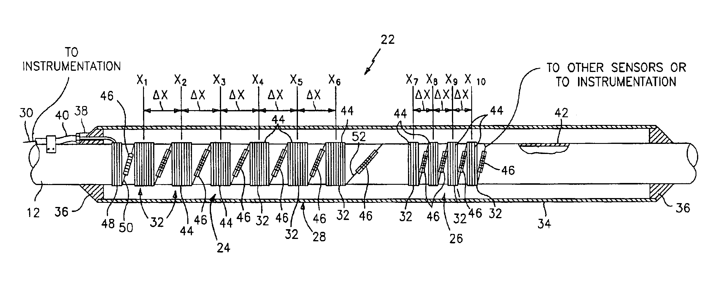
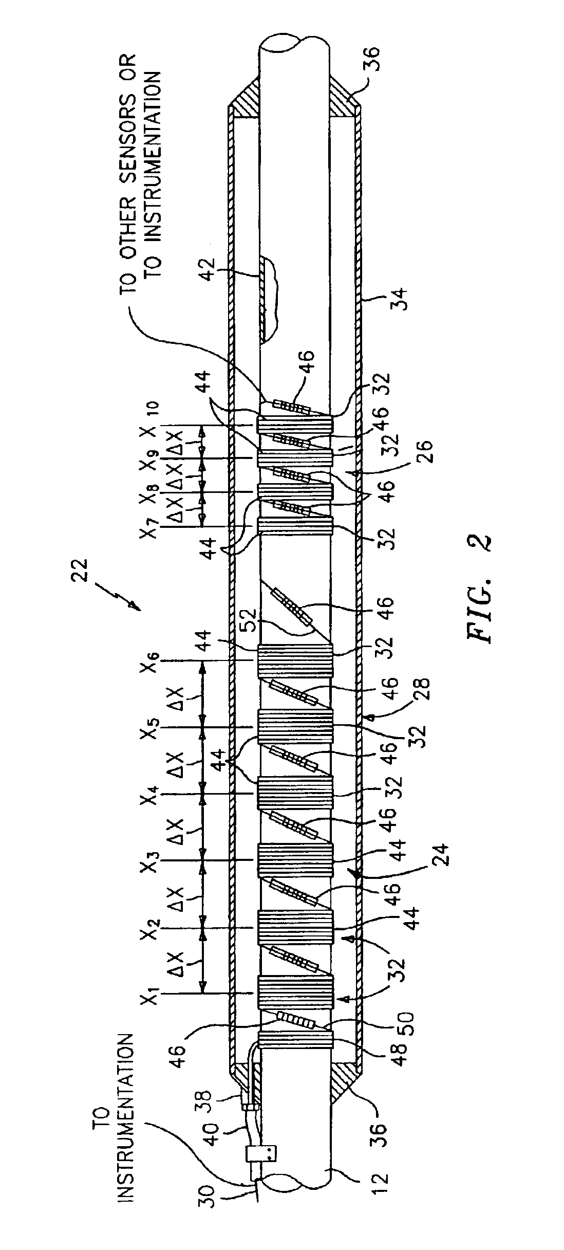
Referring to FIG. 2, the present invention flow meter 22 includes a first sensing array 24 for sensing acoustic signals traveling at the s...


PUM

PropertyMeasurementUnit
diameteraaaaaaaaaa
circumferenceaaaaaaaaaa
lengthaaaaaaaaaa

Abstract

An apparatus for varying the gain of a fiber optic sensor that non-intrusively senses the strain response of a pipe is provided. The apparatus includes a circumferential strain attenuator that has an annular land portion that mechanically couples the attenuator to the pipe. An annular web extends coaxially from the land portion and has a reduced cross sectional area relative to the land, and an annular mandrel portion extends coaxially from the web portion and forms a gap between the pipe and the mandrel. The fiber optic sensor is wound on the circumferential strain attenuator. The web and mandrel cooperate to reduce the strain response of the fiber optic sensor relative to the strain response of the pipe.

Description

BACKGROUND OF THE INVENTION1. Technical FieldThis invention relates to fluid flow sensing devices that use fiber optics and more particularly to those devices that measure the speed of sound, flow velocity, and other parameters within a pipe using acoustic signals and local short duration pressure variations within the flow.2. Background InformationIn the petroleum industry, there is considerable value in the ability to monitor the flow of petroleum products in the production pipe of a well in real time. Historically, flow parameters such as the bulk velocity of a fluid have been sensed with venturi type devices directly disposed within the fluid flow. These type devices have several drawbacks including that they provide an undesirable flow impediment, are subject to the hostile environment within the pipe, and typically provide undesirable potential leak paths into or out of the pipe. In addition, these type devices are also only able to provide information relating to the bulk flu...

Claims


Application Information

Patent Timeline
Patent Type & Authority Patents(United States)
IPC IPC(8): G01F1/00G01D5/26G01H9/00G01V1/52G01V1/40
CPCG01D5/268G01F1/00G01V1/523G01L1/246G01H9/004
Inventor CROTEAU, PAUL F.GYSLING, DANIEL L.DIENER, JAMES M.
Owner WEATHERFORD TECH HLDG LLC
Why Eureka
Try Eureka